Recessed downlight fixture and method for installing the fixture and adjusting the fixture collar opening

Active Publication Date: 2017-10-05
LUTRON TECH CO LLC
View PDF0 Cites 5 Cited by
  • Summary
  • Abstract
  • Description
  • Claims
  • Application Information

AI Technical Summary

Benefits of technology

This patent describes an LED recessed downlight fixture that can be retrofitted into existing incandescent or fluorescent fixtures, and compensates for changes in LED illumination patterns and sub-optimal placement of the previous fixtures. The fixture allows for adjustment of the light source relative to the fixture, allowing for illumination from the LEDs in any pattern. This provides three degrees of movement, or universal adjustment, in a retrofit or new construction application to accommodate any LED illumination pattern within a downlight fixture. The fixture also ensures that all collars are in a straight row, which is easy to adjust for alignment in a new construction application or after the ceiling is installed.

Problems solved by technology

The recessed light fixtures, while moveable on the parallel hanger bars between the ceiling joists, and also moveable in the vertical line for adjustment relative to the ceiling, the conventional recessed downlight fixture typically does not allow adjustment of the light source relative to the fixture.
Instead, conventional recessed downlight fixtures only allow the light source to illuminate straight down along the vertical line once the fixture is secured to the hanger brackets.
The limited adjustment of a downlight fixture is increasingly problematic as the ceiling space or ceiling plenum becomes crowded.
It sometimes occurs that the recessed interior downlight fixture cannot be installed in an optimal location because of such impediments in the ceiling space.
Yet, the light source of a typical downlight fixture that has no adjustment capability must be directed to possibly an undesired location if the fixture is not optimally mounted on the hanger brackets and hanger bars.
This problem is even more acute when replacing incandescent or fluorescent recessed downlight fixtures with LED recessed downlight fixtures, since it is even more desirable to change the LED illumination pattern relative to the prior incandescent illumination pattern due to the difference in illumination between LEDs and incandescence or fluorescent lighting sources.

Method used


Image

  • Recessed downlight fixture and method for installing the fixture and adjusting the fixture collar opening
  • Recessed downlight fixture and method for installing the fixture and adjusting the fixture collar opening
  • Recessed downlight fixture and method for installing the fixture and adjusting the fixture collar opening

Examples


first embodiment

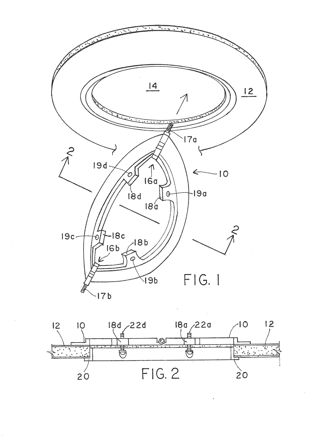
[0041]Beginning with the first embodiment, and referring to FIG. 1, a foldable ring 10 is shown insertable through an opening in a ceiling 12. The opening 14 results from the extraction of a previously placed recessed downlight fixture associated with, for example, an incandescent or fluorescent fixture in favor of a to-be installed LED recessed downlight fixture, for example. Alternatively, opening 14 could also be in a newly created opening in a ceiling where there may have not been any previously installed fixture and thus not necessarily used to replace an existing light fixture. In order to install the new LED recessed downlight fixture into opening 14, retaining ring must be inserted into the opening 14 which pre-exists or is created within the ceiling 12 without disrupting ceiling 12. Accordingly, ring 10 must be foldable upon itself.

[0042]Foldable ring 10 includes two axis 16a and 16b about which ring 10 folds onto itself. Ring 10 can either be of circular, square or rectang...

second embodiment

[0054]FIGS. 6-9 illustrate a second embodiment in which a recessed downlight fixture is applied to a new construction application in which a ceiling is not yet present. Instead, all that is present during install is at least one ceiling joist 100. Ceiling joist 100 is exposed from below, and either exists as a subfloor of the room above, or in the attic, along with ventilation ducts, fire sprinkler systems, conduits of various kinds for data cables, etc.

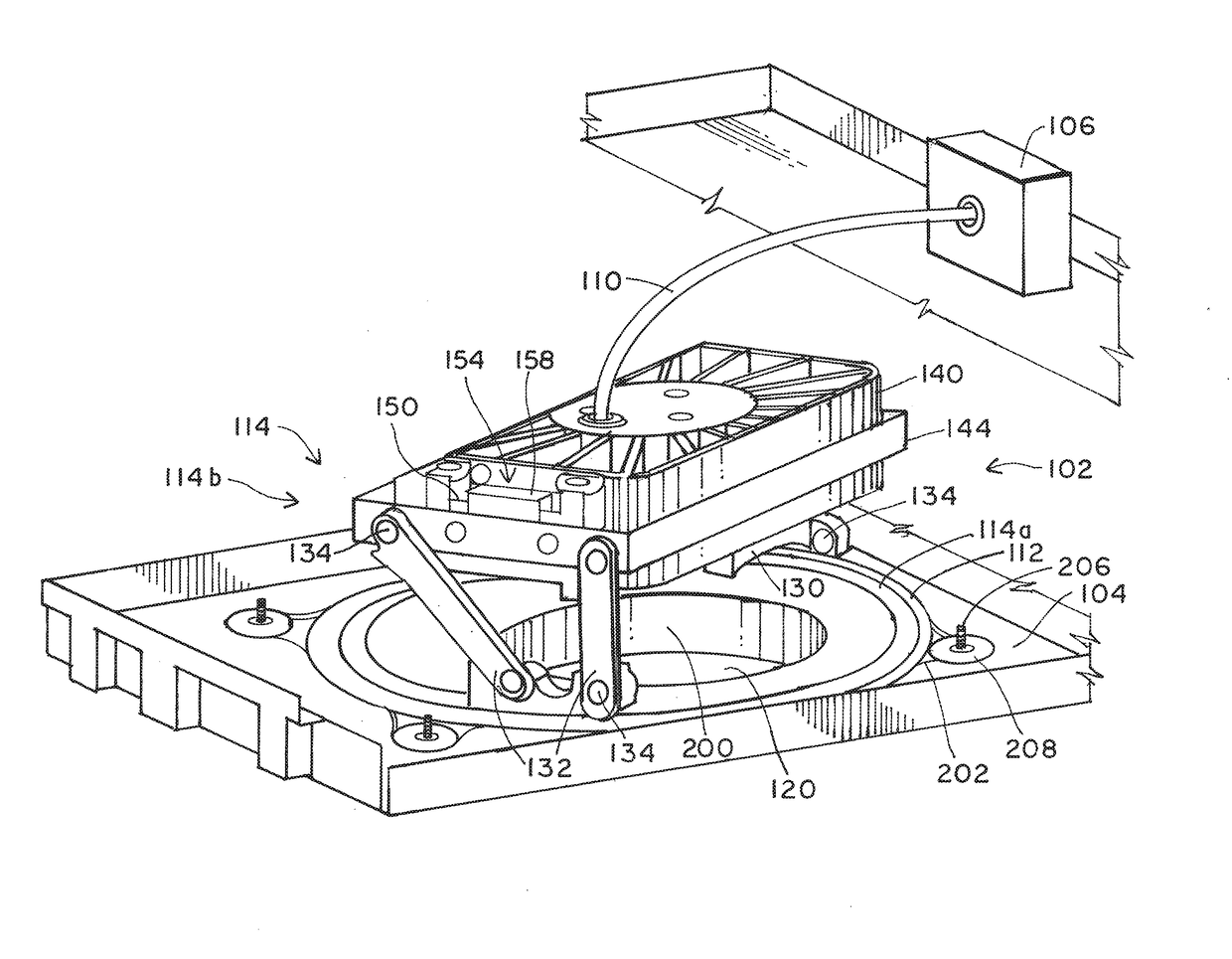
[0055]A recessed downlight fixture 102 for use in a new construction application can be coupled to a single ceiling joist 100a, or coupled to a spaced apart pair of ceiling joists 100a and 100b, as shown in FIG. 6. Fixture 102 includes a plate 104, possibly having a junction box 106 and other elements of downlight fixture 102, labeled 108. Those other elements will be described in more detail with reference to FIGS. 7-9. Similar to the first embodiment for the retrofit application, the second embodiment for a new construction applica...

third embodiment

[0070]The recessed downlight fixture therefore includes a luminaire housing that is rotatable within the circular base and tiltable relative to the circular base, and also includes a second plate moveably secured on the second planar surface of plate 104 and coupled to a collar 200 dimensioned to form an aperture that extends through the plate and the second plate as well as the circular base 112. The collar 200 is moveable within a plane, as well as rotatably moveable between the second plate 212 and the luminaire housing by at least one screw 226 configured to be placed into a threaded opening in the collar and frictionally engage against the second plate. At least one screw 206 that is placed through the second plate is placed at least into a threaded washer 208 that when the screw is tightened, the threaded washer 208 frictionally bears again the first planar surface of plate 104. The collar is moved from below the plate while standing in a room, for example. The collar is move...


PUM


Abstract

A recessed downlight fixture and method for installation is provided. The recessed downlight fixture can be installed in a retrofit application, after a ceiling is installed, through a pre-existing opening in that ceiling. Alternatively, a recessed downlight fixture according to a second embodiment can be installed before a ceiling is present. In either embodiment, the light source coupled to, for example, a heat sink, can be universally moved in three degrees of movement, rotationally, along a tilt axis, or further within the ceiling to increase or decrease the recess. All such universal adjustments can take place through and below the ceiling opening during or after installation.

Description

RELATED APPLICATIONS[0001]This application is related to co-pending applications filed concurrently herewith under Ser. No. 15 / 088,813, entitled “Recessed Downlight Fixture and Method for Installing and Universally Adjusting the Fixture in a Retrofit Application”, and Ser. No. 15 / 088,864, entitled “Recessed Downlight Fixture and Method for Installing and Universally Adjusting the Fixture in a New Construction Application.”BACKGROUND OF THE INVENTION1. Field of the Invention[0002]This invention relates to the field of interior lighting and, more particularly, to recessed downlight fixtures that can accommodate three degrees of adjustment below and through an opening in either a retrofit or new construction application.2. Description of the Relevant Art[0003]Lighting within a structure, such as a residential or commercial structure, is generally referred to as interior lighting. Contrary to interior lighting, lighting can also be employed exterior of the structure. Exterior lighting i...

Claims


Application Information

Patent Timeline
IPC IPC(8): F21S8/02F21V29/503F21V23/02F21V17/10F21V21/04F21V23/06
CPCF21S8/026F21V21/049F21V23/06F21Y2115/10F21S8/028F21V17/105F21V29/503F21V23/026F21V21/042
Inventor COAKLEY, STEVEN F.MICHALKO, JOHN P.LOGAN, DEREK E.
Owner LUTRON TECH CO LLC
Why Eureka
Try Eureka