Fluid control apparatus

a control apparatus and flue gas technology, applied in the direction of electrical apparatus casings/cabinets/drawers, coupling device connections, instruments, etc., can solve the problems of low work efficiency and low ease of work

Inactive Publication Date: 2017-10-05
HORIBA STEC CO LTD
View PDF3 Cites 2 Cited by
  • Summary
  • Abstract
  • Description
  • Claims
  • Application Information

AI Technical Summary

Benefits of technology

[0022]According to the present invention so configured, even when the fluid control apparatuses are disposed adjacent to each other, it is possible to effortlessly connect the cable to each of the fluid control apparatuses.

Problems solved by technology

This can cause the following problems.
That is, for example, when taking out one of the mass flow controllers disposed adjacent to each other without any clearance therebetween, or when adjacently disposing other mass flow controller between two mass flow controllers, ease of work can become very low when an operation is carried out while the cables are in place, and working efficiency can become very low when the operation is carried out while attaching and detaching the cables one by one.

Method used


Image

  • Fluid control apparatus
  • Fluid control apparatus
  • Fluid control apparatus

Examples


Embodiment Construction

[0030]An embodiment of a fluid control apparatus according to the present invention is described below with reference to the drawings.

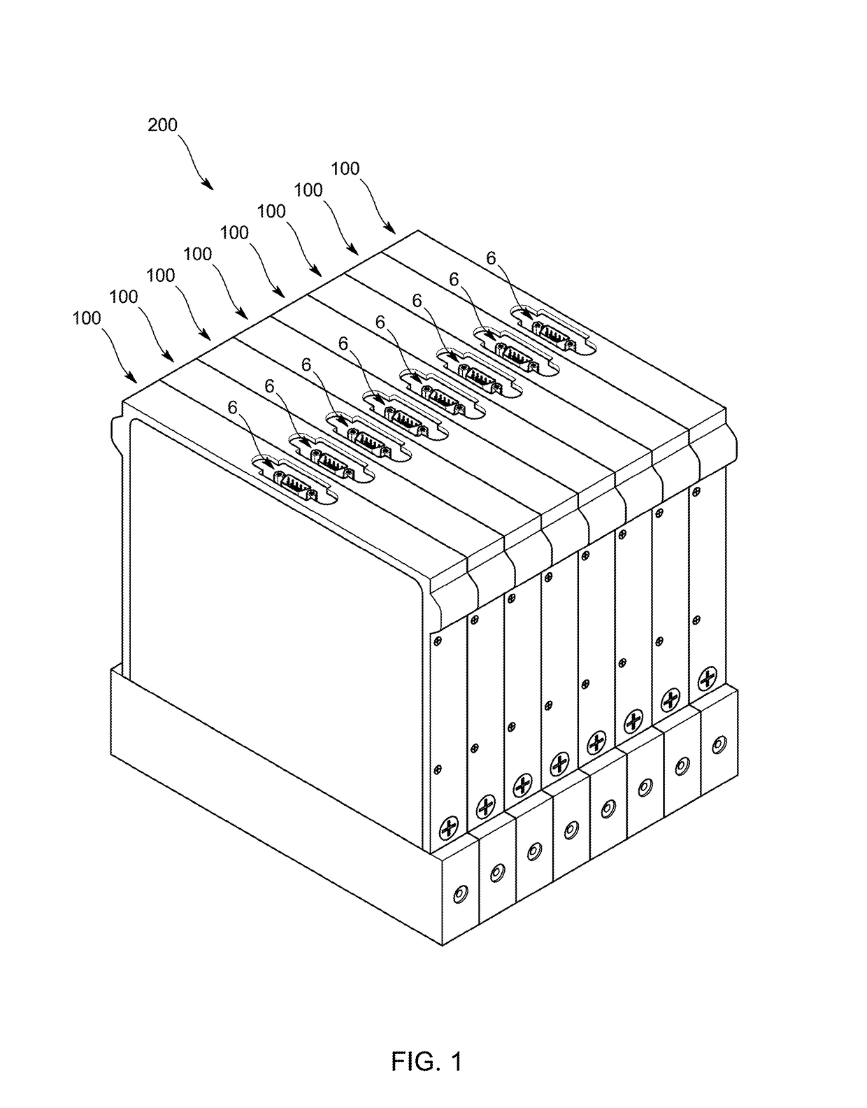
[0031]As shown in FIG. 1, the fluid control apparatuses 100 of the present embodiment constitute a fluid control system 200 for use in, for example, a semiconductor manufacturing process using a plurality of gases, and are respectively disposed on a plurality of gas lines so as to independently control physical properties of fluids passing through the gas lines, such as a flow rate, pressure, temperature, and viscosity.

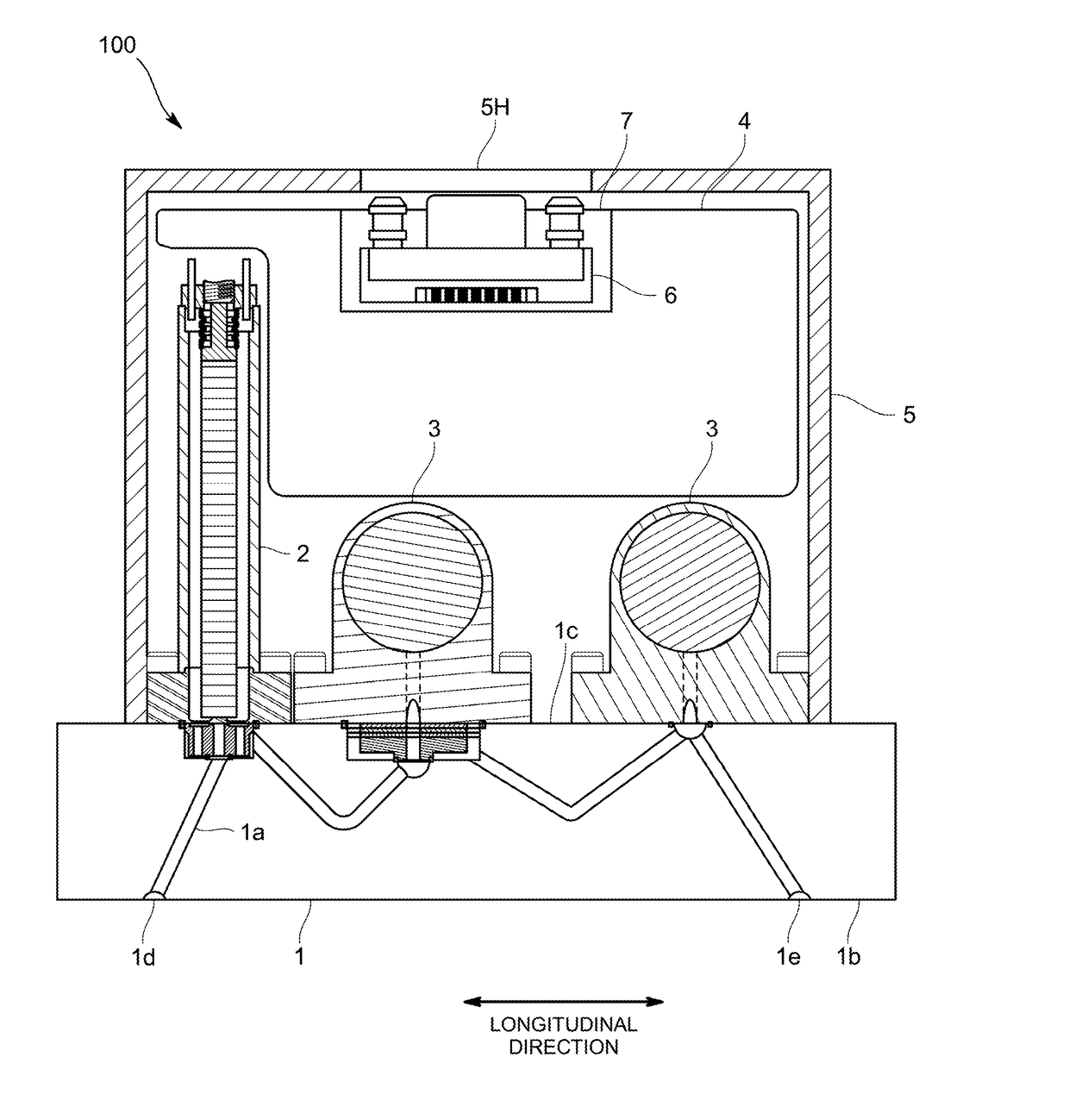
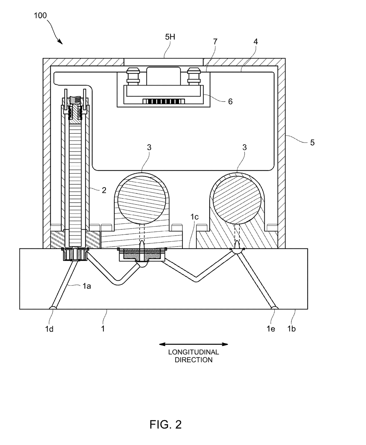
[0032]To be specific, as shown in FIG. 2, the fluid control apparatus 100 includes a body 1, a flow rate control valve 2, a pressure sensor 3, an electric circuit board 4, and a casing 5. The body 1 includes an internal flow channel 1a configured to pass a fluid therethrough. The flow rate control valve 2 is fluid equipment disposed on the internal flow channel 1a. The pressure sensor 3 is fluid equipment disposed downstream of the flow...


PUM


Abstract

A fluid control apparatus is provided which makes it possible to effortlessly perform cable connection even when a plurality of the fluid control apparatuses are disposed adjacent to each other. The fluid control apparatus includes fluid control units to control a flow rate or pressure of a fluid, an electric circuit board to send and receive a signal to and from the fluid control units, a casing to accommodate therein the fluid control units and the electric circuit board, and an apparatus-side connector interposed between the electric circuit board and a cable electrically connected thereto. The fluid control apparatus further includes a connector board configured to mount thereon the apparatus-side connector. The connector board is secured to the electric circuit board with at least a part of the connector board in surface contact with the electric circuit board, or overlapping the electric circuit board with a clearance therebetween.

Description

FIELD OF THE INVENTION[0001]The present invention relates to a fluid control apparatus configured to measure and control a fluid, such as a material gas for use in a semiconductor process.BACKGROUND ART[0002]For example, a mass flow controller that is this type of fluid control apparatus includes fluid control units, such as a flow rate sensor and a flow rate control valve, an electric circuit board to send and receive a signal to and from these fluid control units, and a casing to accommodate therein the fluid control units and the electric circuit board, as disclosed in Patent Document 1. The mass flow controller is configured to be connected with a cable to, for example, a user-side information processor via a connector disposed on the electric circuit board.[0003]Recently, thinning of the fluid control apparatus, such as the mass flow controller, is desired for reducing an installation area. Hence, for example, the present inventors have been developing a mass flow controller ha...

Claims


Application Information

Patent Timeline
Patent Type & Authority Applications(United States)
IPC IPC(8): G05D7/06H01R12/71H05K1/14H01R12/75H05K5/00H05K1/18
CPCG05D7/0635H05K5/0069H05K1/181H05K1/148H05K2201/048H01R12/75H01R12/716H05K2201/09145H05K2201/09072H05K1/141H05K1/117H05K3/368H05K2201/041H05K2201/049H05K2201/09181H05K2201/10189H05K2201/10287H01R12/00Y02P70/50H01R12/712H01R12/732H05K1/14H05K1/142H05K1/145H05K2201/043
Inventor OHTANI, KATSUYA
Owner HORIBA STEC CO LTD
Why Eureka
Try Eureka