Electrical Connector

Active Publication Date: 2017-10-12
KUNSHAN DRAPHO ELECTRONICS TECH
View PDF1 Cites 7 Cited by
  • Summary
  • Abstract
  • Description
  • Claims
  • Application Information

AI Technical Summary

Benefits of technology

The present invention provides an electrical connector with improved grounding terminals to reduce crosstalk between signal terminals. Each grounding terminal is formed by bending a linear wire and includes an upper contacting portion, a bending portion, and a lower contacting portion. A shielding plate is located between the upper and lower contacting portions and is in contact with the bending portion. This reduces crosstalk between the upper-row signal terminals and the lower-row signal terminals and enhances the shielding effect.

Problems solved by technology

However, the existing Type C connector still has a serious crosstalk problem in a process of transmitting data, thereby affecting the transmission speed of data.
The assembly process is complicated, and the cost is increased.

Method used


Image

  • Electrical Connector
  • Electrical Connector
  • Electrical Connector

Examples


Embodiment Construction

[0015]The following description is presented to enable a person of ordinary skill in the art to make and use the various embodiments. Descriptions of specific devices, techniques, and applications are provided only as examples. Various modifications to the examples described herein will be readily apparent to those of ordinary skill in the art, and the general principles defined herein may be applied to other examples and applications without departing from the spirit and scope of the various embodiments. Thus, the various embodiments are not intended to be limited to the examples described herein and shown, but are to be accorded the scope consistent with the claims.

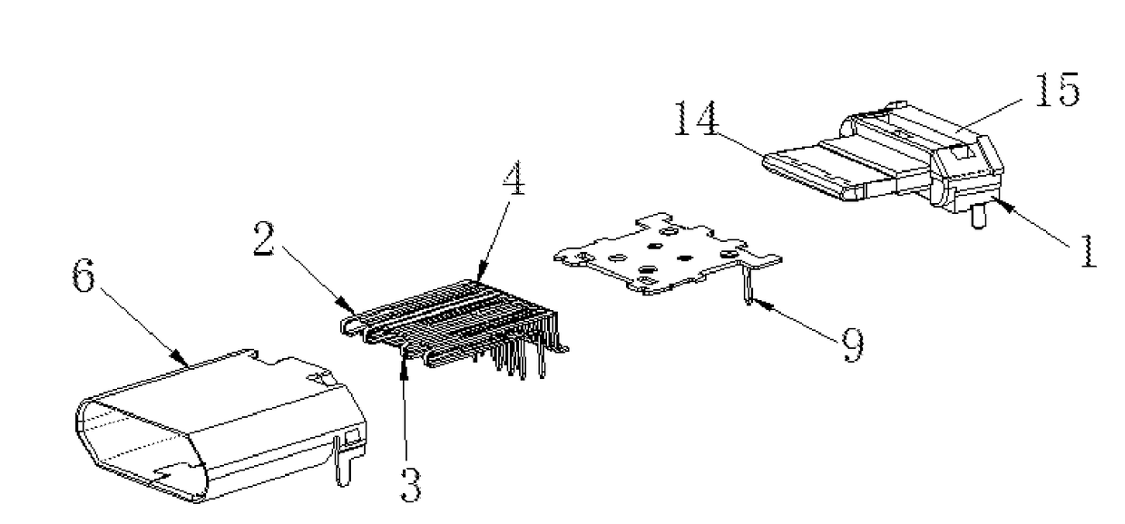
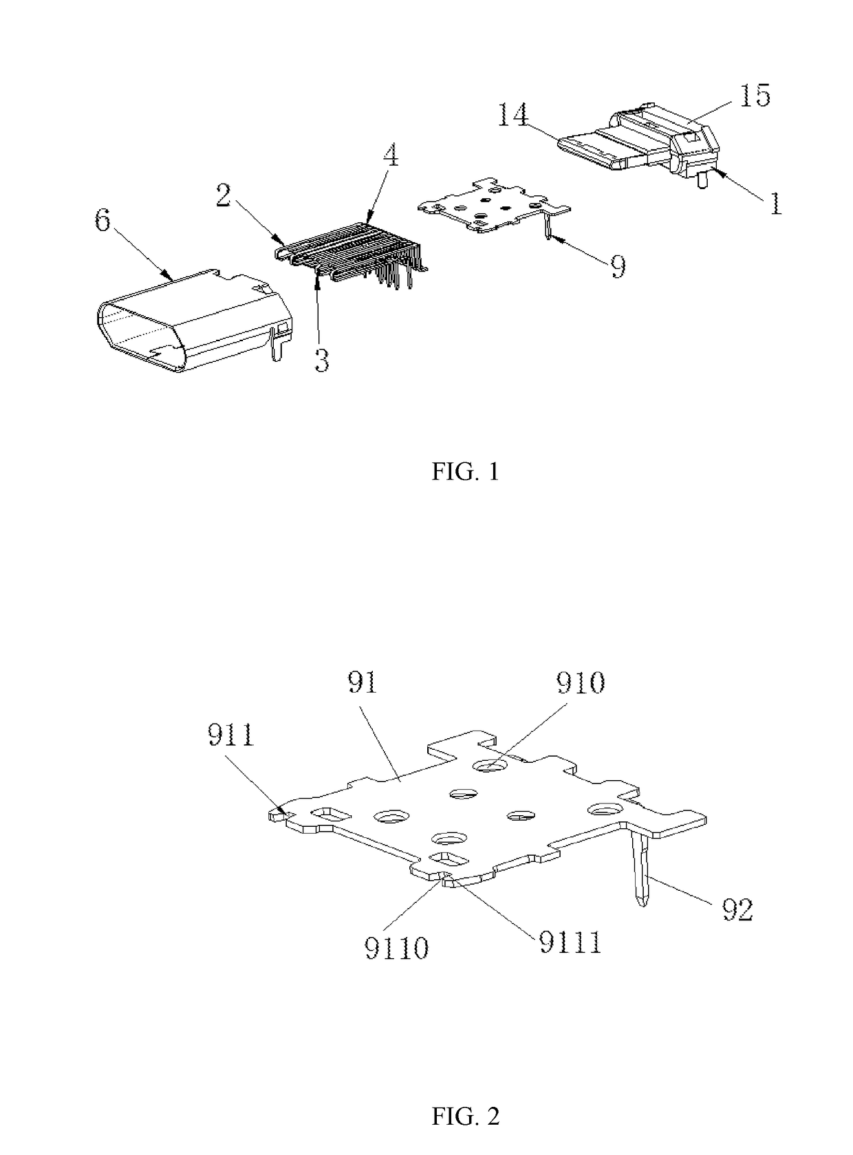
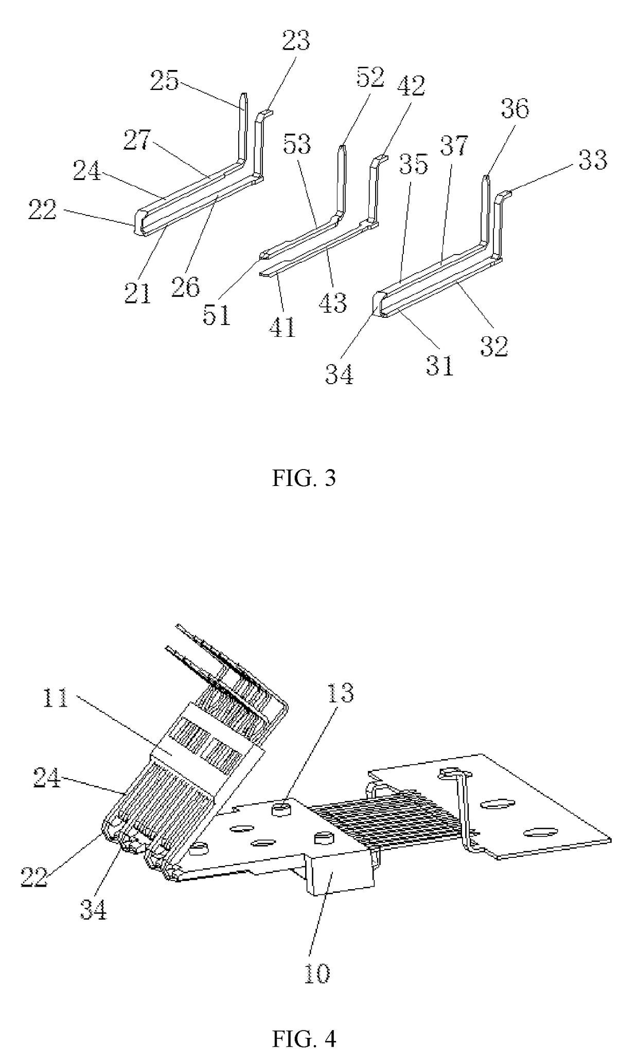
[0016]Referring to FIG. 1 to FIG. 7, an electrical connector of the present invention comprises an insulation body 1, a shielding plate 9, a plurality of grounding terminals 2 and conducting terminals accommodated inside the insulation body 1, and a shell 6 surrounding the periphery of the insulation body 1. The conduct...


PUM


Abstract

The present invention relates to an electrical connector, which has an insulation body, a shielding plate, a plurality of grounding terminals and conducting terminals accommodated in the insulation body. Each grounding terminal is formed by bending a linear wire and has an upper contacting portion, a bending portion extending from the upper contacting portion, and a lower contacting portion extending from the bending portion, wherein the upper contacting portion is parallel to the lower contacting portion. Therefore, the crosstalk between the upper-row signal terminals and the lower-row signal terminals is reduced, and the shielding effect is enhanced.

Description

RELATED APPLICATIONS[0001]The present application claims priority under 35 U.S.C. §119 to People's republic of China Patent Application 2016102147298, which was filed on Apr. 8, 2016, the entire contents of which are incorporated herein by reference.FIELD OF THE INVENTION[0002]The present invention relates to an electrical connector, in particular to an electrical connector having improved grounding terminals.BACKGROUND[0003]An existing Type C connector comprises an insulation boy, a plurality of upper-row terminals and a plurality of lower-row terminals assembled to the insulation body, a shielding plate located between the lower-row terminals and the upper-row terminals, and a shell surrounding the periphery of the insulation body. The upper-row terminals include upper-row grounding terminals, upper-row signal terminals and upper-row power terminals. The lower-row terminals include lower-row grounding terminals, lower-row signal terminals and lower-row power terminals. The shieldi...

Claims


Application Information

Patent Timeline
IPC IPC(8): H01R13/6597H01R24/60
CPCH01R13/6597H01R2107/00H01R24/60H01R13/02H01R13/648H01R13/6585H01R12/724
Inventor FANG, ZHIHONGMO, ZHIJIANWU, ZHUPINGSHAN, LINA
Owner KUNSHAN DRAPHO ELECTRONICS TECH
Why Eureka
Try Eureka