Pneumatic tire

a technology of pneumatic tires and sealants, which is applied in the field of pneumatic tires, can solve the problems of vibration or insufficient sealing performance, insufficient adhesion of sealants to the inner periphery of tires, and insufficient sealing performance, and achieve the effect of sufficient sealing performan

Active Publication Date: 2017-10-19
SUMITOMO RUBBER IND LTD
View PDF0 Cites 10 Cited by
  • Summary
  • Abstract
  • Description
  • Claims
  • Application Information

AI Technical Summary

Benefits of technology

[0030]The pneumatic tire (self-sealing tire) of the present invention is a self-sealing tire including a sealant layer located radially inside an innerliner. The sealant layer is formed by applying a sealant to the inner periphery of a tire from which mold release agents have been removed. Such a pneumatic tire has sufficient sealing performance.

Problems solved by technology

However, since the sealants have a certain level of viscosity so as to be prevented from flowing, they may show insufficient adhesion.
For this reason, the sealants are difficult to attach to the inner peripheries of tires in some cases.
As a result of extensive studies, the present inventors have found that mold release agents are usually applied to the inner peripheries of tires to avoid adhesion between the bladder and the tire during vulcanization, and unfortunately the presence of such mold release agents may hinder successful application of sealants to the tires during the sealant application or may cause dislocation or separation of the sealants during service, thereby resulting in vibration or insufficient sealing performance.
The present inventors made further extensive studies and have found that by applying a sealant to the inner periphery of a tire from which mold release agents have been removed, the adhesion between the sealant and the inner periphery of the tire is improved, and therefore the sealant can be successfully applied to the inner periphery of the tire in the sealant application, and does not dislocate or separate during service, thereby causing no vibration but providing sufficient sealing performance.

Method used


Image

  • Pneumatic tire
  • Pneumatic tire
  • Pneumatic tire

Examples


first embodiment

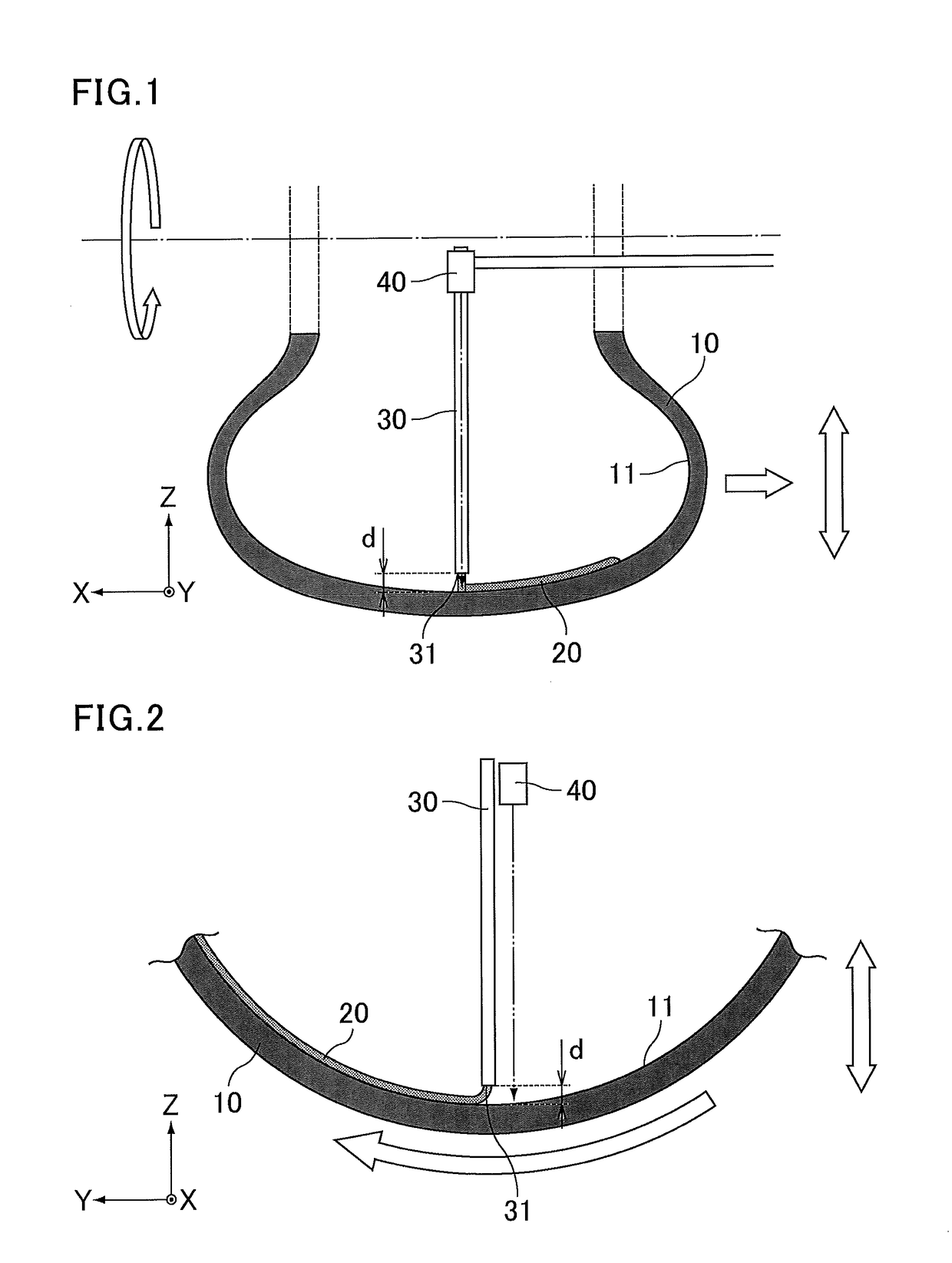
[0126]According to a first embodiment, a self-sealing tire can be produced, for example, by performing the Steps (1), (2), and (3) below in the process of applying an adhesive sealant through a nozzle to the inner periphery of a tire while rotating the tire and simultaneously moving at least one of the tire and nozzle in the width direction of the tire: Step (1) of measuring the distance between the inner periphery of the tire and the tip of the nozzle using a non-contact displacement sensor; Step (2) of moving at least one of the tire and nozzle in the radial direction of the tire according to the measurement to adjust the distance between the inner periphery of the tire and the tip of the nozzle to a predetermined length; and Step (3) of applying the sealant to the inner periphery of the tire after the distance is adjusted.

[0127]The distance between the inner periphery of the tire and the tip of the nozzle can be maintained at a constant length by measuring the distance between th...

second embodiment

[0188]The studies of the present inventors have further revealed that the use of the method according to the first embodiment alone has the following disadvantage: a sealant having a generally string shape is occasionally difficult to attach to the inner periphery of a tire and can easily peel off especially at the attachment start portion. A second embodiment is characterized in that in the method for producing a self-sealing tire, the sealant is attached under conditions where the distance between the inner periphery of the tire and the tip of the nozzle is adjusted to a distance d1 and then to a distance d2 larger than the distance d1. In this case, the distance between the inner periphery of the tire and the tip of the nozzle is shortened at the beginning of the attachment, so that the width of the sealant corresponding to the attachment start portion can be increased. As a result, a self-sealing tire can be easily produced in which a generally string-shaped adhesive sealant is ...

third embodiment

[0219]The studies of the present inventors have further revealed that the use of the method according to the first embodiment alone has the following disadvantage: a sealant having a generally string shape is occasionally difficult to attach to the inner periphery of a tire and can easily peel off especially at the attachment start portion. The studies of the present inventors have still further revealed that, if the attachment start portion of the sealant is peeled, unfortunately the peeled portion may not show sufficient sealing performance, and thus sufficient sealing performance cannot be obtained on the entire sealant layer.

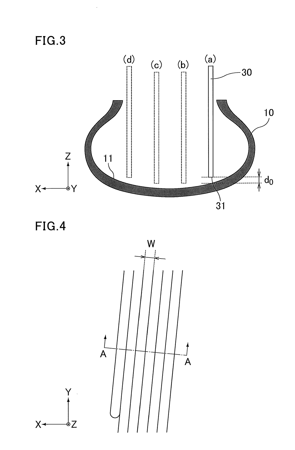
[0220]In order to solve these problems, the attachment start portion of the sealant is adapted to be located tire-widthwise inward from the tire-widthwise end of the sealant layer as shown in FIG. 10(d). This allows the entire sealant layer to have sufficient sealing performance even when the attachment start portion of the sealant is peeled.

[0221]More speci...


PUM

PropertyMeasurementUnit
temperatureaaaaaaaaaa
widthaaaaaaaaaa
areaaaaaaaaaaa

Abstract

Provided is a pneumatic tire having sufficient sealing performance. The present invention relates to a pneumatic tire including a sealant layer located radially inside an innerliner, the sealant layer being formed by applying a sealant to the inner periphery of a tire from which mold release agents have been removed.

Description

TECHNICAL FIELD[0001]The present invention relates to a pneumatic tire.BACKGROUND ART[0002]Self-sealing tires with sealants applied to the inner peripheries thereof have been known as puncture resistant pneumatic tires (hereinafter, pneumatic tires are also referred to simply as tires). Sealants automatically seal puncture holes formed in such self-sealing tires.[0003]Several methods have been known for producing self-sealing tires, including, for example, a method that includes: adding an organic solvent to a sealant to reduce the viscosity of the sealant so as to be easy to handle; attaching the diluted sealant to the inner surface of a tire; and removing the organic solvent from the attached diluted sealant, and a method that includes: mixing a base agent prepared in a batch kneader with a curing agent using a static mixer or dynamic mixer to prepare a sealant; and attaching the sealant to the inner periphery of a tire (see, for example, Patent Literature 1).[0004]Patent Literatu...

Claims


Application Information

Patent Timeline
Patent Type & Authority Applications(United States)
IPC IPC(8): B29C73/22B60C5/14B60C1/00B60C5/16B29C73/16
CPCB29C73/22B60C1/0008B29C73/163B60C5/14B60C5/16B60C19/12B60C5/00B29D30/0685B29D2030/0686B29D2030/0694B60C2200/10B29D30/0061B60C19/002B29D2030/0697B60C2009/0441B60C2009/0466B60C9/0007B29D30/0681Y10T152/10684B60C11/1353C08L23/22C08L2203/162C08L2205/025C08L2205/03B60C19/122
Inventor YUKAWA, NAOKISUGIMOTO, MUTSUKIYAMADA, SATOSHI
Owner SUMITOMO RUBBER IND LTD
Why Eureka
Try Eureka