Method of producing a sliding sleeve for a synchronous manual transmission assembly and sliding sleeve produced by means of the method

a technology of synchronous manual transmission and method, which is applied in the direction of metal rolling, mechanical equipment, clutches, etc., can solve the problems of comparatively high cost, and achieve the effect of high hardness and high level of wear resistan

Active Publication Date: 2017-10-19
HOERBIGER ANTRIEBSTECHN HLDG
View PDF15 Cites 4 Cited by
  • Summary
  • Abstract
  • Description
  • Claims
  • Application Information

AI Technical Summary

Benefits of technology

[0012]Preferably, provision is made that the internal toothing arrangement is produced by means of plastic deformation of the blank. Apart from the fact that material usage is hereby reduced in comparison with a machining method, the stability of the sliding sleeve is increased by reason of the cold work hardening of the material during deformation.
[0013]According to one embodiment of the invention, provision is made that the internal toothing is produced by means of a pilgering method, in particular a cold pilgering method. This method is very suitable for producing the toothing arrangement with a small amount of outlay and a high level of precision.
[0014]During pilgering, a pilger mandrel is preferably used which has different pitches. This renders it possible to produce the different tooth shapes of the blank and thus also of the sliding sleeve with the same mandrel.
[0019]The outer contour can also be introduced by means of plastic deformation. As a result, it is possible to produce both a groove on the outer circumference of the sliding sleeve and also a ring which protrudes in the radial direction.
[0022]Provision can also be made that the sliding sleeve is thermally treated, in particular is hardened. As a result, a high level of hardness and thus a high level of wear resistance can be achieved either over the entire surface of the sliding sleeve or even only in the regions subjected to particular loading in each case (e.g. the internal toothing arrangement).

Problems solved by technology

This gives rise to comparatively high costs.

Method used


Image

  • Method of producing a sliding sleeve for a synchronous manual transmission assembly and sliding sleeve produced by means of the method
  • Method of producing a sliding sleeve for a synchronous manual transmission assembly and sliding sleeve produced by means of the method
  • Method of producing a sliding sleeve for a synchronous manual transmission assembly and sliding sleeve produced by means of the method

Examples


Embodiment Construction

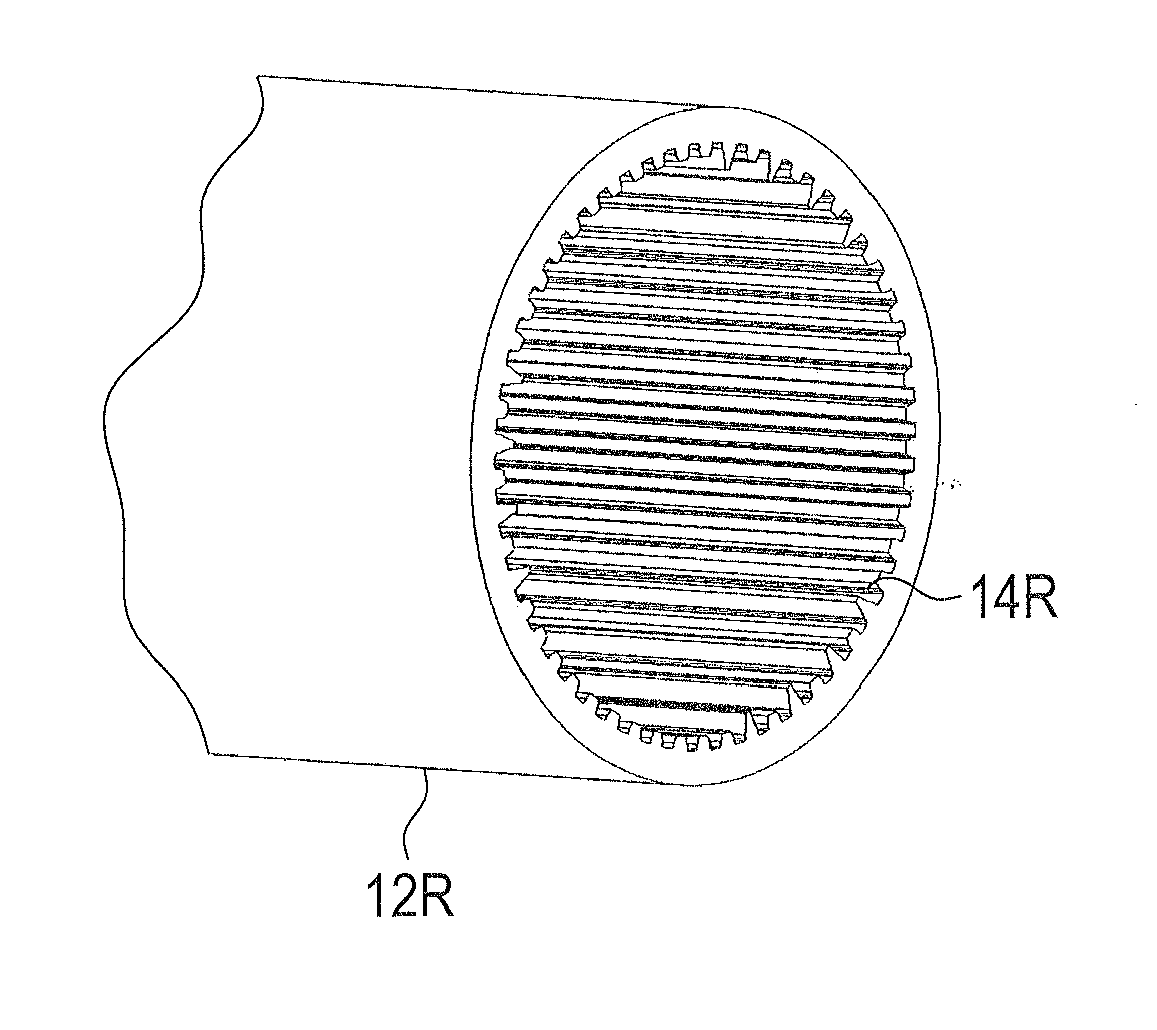
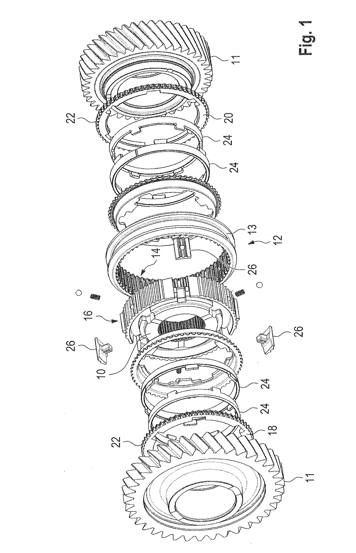
[0033]The production of a sliding sleeve 12, as can be used in a synchronous manual transmission assembly shown in FIG. 1, will be explained hereinafter with reference to FIGS. 2 to 9.

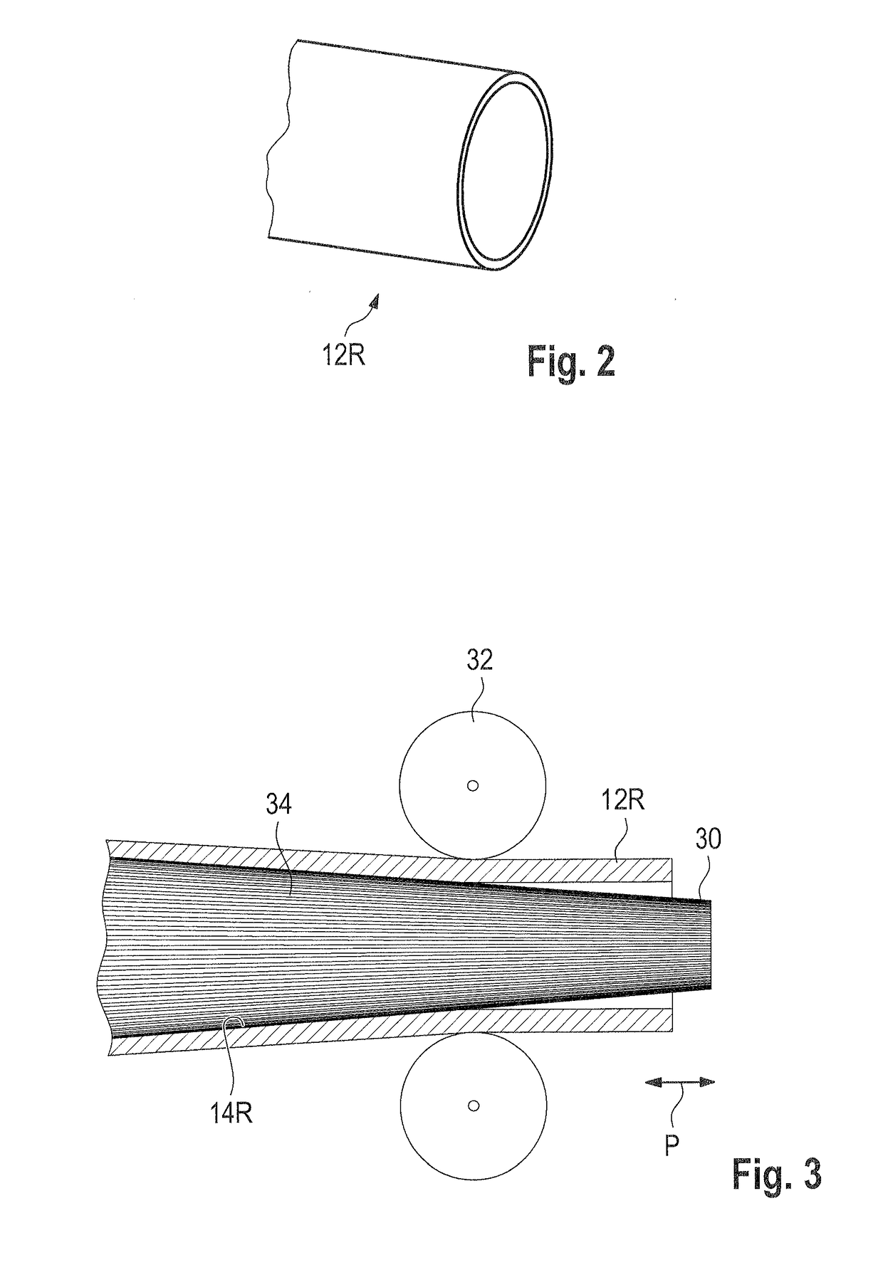
[0034]In a first step, a blank 12R is provided which is a tube consisting of a metal alloy, in particular case-hardened steel or carbon steel. The tube is seamless. If the blank 12R is a tube comprising a smooth inner surface or is a tube whose inner profiling does not correspond to the internal toothing arrangement of the sliding sleeve to be produced, the blank 12R is provided with an internal toothing arrangement 14R in a second method step. For this purpose, the blank 12R is plastically deformed.

[0035]The blank 12R is dimensioned in such a manner that after the subsequent further processing steps the sliding sleeve is produced with the desired dimensions.

[0036]In one embodiment (see FIG. 3), the second method step consists of cold-pilgering the blank 12R. For this purpose, a pilger mandrel 30 and a...


PUM

PropertyMeasurementUnit
plastic deformationaaaaaaaaaa
widthaaaaaaaaaa
heightaaaaaaaaaa

Abstract

A sliding sleeve for a synchronous manual transmission assembly is produced by the following steps:a tubular blank is provided in which an internal toothing arrangement is present, andthe blank which is provided with the internal toothing arrangement is further processed to form a plurality of sliding sleeves.

Description

[0001]The invention relates to a method of producing a sliding sleeve for a synchronous manual transmission assembly and to a sliding sleeve produced by such a method.BACKGROUND OF THE INVENTION[0002]A synchronous manual transmission assembly serves to couple loose wheels of transmission stages (“gears”) of a manual transmission comprising a transmission shaft when the appropriate gear is to be selected. An example of such a synchronous assembly is shown schematically in FIG. 1.[0003]The synchronous assembly contains a synchroniser hub 10 which is arranged on a transmission shaft for conjoint rotation therewith. Arranged on the synchroniser hub is a sliding sleeve 12 which can be displaced relative to the synchroniser hub 10 in the axial direction but is fixed for conjoint rotation therewith in the circumferential direction. For this purpose, the sliding sleeve 12 is provided with an internal toothing arrangement 14 which can be displaced axially but in the circumferential direction...

Claims


Application Information

Patent Timeline
Patent Type & Authority Applications(United States)
IPC IPC(8): F16D23/06B21B21/00B21B25/00
CPCF16D23/06B21B21/00B21B25/00F16D2250/0023F16D2250/0038F16D2200/0021F16D2023/0631B23P15/14F16D2023/0656Y10T29/49798
Inventor DAMM, ANSGARHOLZHEU, GEORGKLEINER, STEFANLAUER, BJOERNTHAU, HERMANN
Owner HOERBIGER ANTRIEBSTECHN HLDG
Why Eureka
Try Eureka