X-ray tube and a conditioning method thereof

Active Publication Date: 2017-10-19
NANO X IMAGING LTD
View PDF1 Cites 1 Cited by
  • Summary
  • Abstract
  • Description
  • Claims
  • Application Information

AI Technical Summary

Benefits of technology

[0003]However, when a cold cathode source is used as an electron emission source, there is a problem that electron emission is easily affected by the degree of vacuum of an X-ray tube during its operation because the electron emission is sensitive to a surface state of the cathode compared to a hot cathode. Particularly, it is known that in a Spindt-type cold cathode array using a molybdenum (Mo) material, a current

Problems solved by technology

However, when a cold cathode source is used as an electron emission source, there is a problem that electron emission is easily affected by the degree of vacuum of an X-ray tube during its operation because the electron emission is sensitive to a surface state of the cathode compared to a hot cathode.
Thus, for some situations, there is a problem that decrease in anode current occurs by that the operation of the X-ray tube is conducted continuou

Method used


Image

  • X-ray tube and a conditioning method thereof
  • X-ray tube and a conditioning method thereof

Examples


Example

FIRST EMBODIMENT

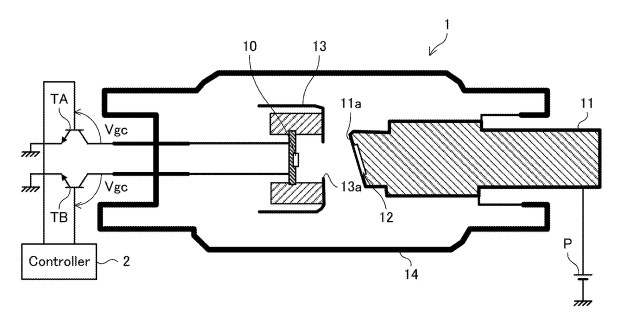
[0016]FIG. 1 is a cross-sectional view schematically illustrating an X-ray tube 1 according to a first embodiment of the present invention. As illustrated in FIG. 1, the X-ray tube 1 has a structure in which an electron emission unit 10, an anode unit 11, a target unit 12, and a focus structure 13 are disposed in a vacuum area surrounded by a glass outer wall 14. FIG. 1 also illustrates a controller 2 for the X-ray tube 1.

[0017]The electron emission unit 10 has an electron emission element using a cold cathode and is configured to emit electrons from the cold cathode. While details will be described later, the electron emission unit 10 is divided into two regions A and B (first and second regions). The regions A and B are grounded through transistors TA and TB, respectively.

[0018]The anode unit 11 is disposed opposite to the electron emission unit 10 and connected to a power supply P. Thus, when either of the transistors TA or TB is turned ON, current flows from the ...

Example

SECOND EMBODIMENT

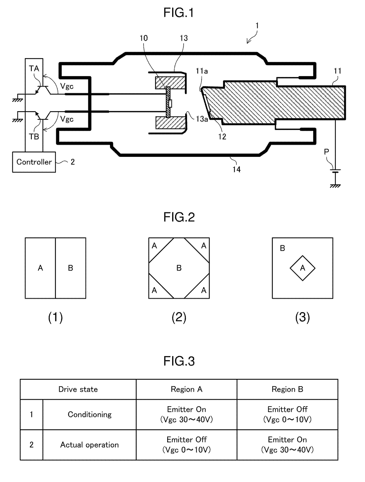
[0028]Next, the second embodiment of the present invention will be described. The second embodiment differs from the first embodiment in the dividing method of the electron emission unit 10. Other configurations are the same as those in the first embodiment. Hereinafter, a description will be given focusing on differences from the first embodiment with the same reference numerals given to the same elements as in the first embodiment.

[0029]FIG. 2(2) is a view illustrating the dividing method of the electron emission unit 10 according to the present embodiment. As illustrated, the electron emission unit 10 according to the present embodiment is divided into two or more regions including a center region and one or more peripheral regions surrounding the center region. Specifically, the electron emission unit 10 is formed into a square shape as in the first embodiment, and the region obtained by concentrically overlapping another square having a size slightly smaller th...


PUM


Abstract

The X-ray tube disclosed herein includes an electron emission unit including an electron emission element using a cold cathode; an anode unit disposed opposite to the electron emission unit, with which electrons emitted from the electron emission unit collide; and a focus structure disposed between the electron emission unit and a target unit disposed on a surface of the anode unit that is opposed to the electron emission unit. The electron emission unit is divided into first and second regions which can independently be turned ON/OFF. The X-ray tube is focus-designed such that collision regions, at the anode unit, of electron beams emitted from the respective first and second regions substantially coincide with each other.

Description

BACKGROUND OF THE INVENTIONField of the Invention[0001]The present invention relates to an X-ray tube and a conditioning method therefor.Description of Related Art[0002]Conventional X-ray tubes use a filament as a cathode and uses thermoelectrons emitted from the filament as an electron source. On the other hand, there are proposed some X-ray tubes that use a cold cathode source as an electron emission element. Such an X-ray tube is disclosed in, e.g., U.S. Pat. No. 7,778,391, U.S. Pat. No. 7,809,114, and U.S. Pat. No. 7,826,595.SUMMARY[0003]However, when a cold cathode source is used as an electron emission source, there is a problem that electron emission is easily affected by the degree of vacuum of an X-ray tube during its operation because the electron emission is sensitive to a surface state of the cathode compared to a hot cathode. Particularly, it is known that in a Spindt-type cold cathode array using a molybdenum (Mo) material, a current decrease occurs due to generation o...

Claims


Application Information

Patent Timeline
IPC IPC(8): H01J35/14H01J35/06H01J35/08H05G1/56
CPCH01J35/14H05G1/56H01J35/08H01J35/065H01J9/39H01J35/20G21K1/025H01J35/112H01J35/153H01J35/147H01J35/04H01J35/064H01J35/045H01J35/06H01J35/066H01J35/025
Inventor KENMOTSU, HIDENORIMASUYA, HITOSHIIIDA, KOICHI
Owner NANO X IMAGING LTD
Why Eureka
Try Eureka