
Bone scaffold improvements

a technology of bone graft and scaffold, which is applied in the field of bone graft improvement and orthopaedic devices, can solve the problems of instrumentation failure and pseudoarthrosis, only possible posterolateral fusion, and inability to deliver bone graft promoting material along the path

Active Publication Date: 2017-10-26
PEDOULIAS PANAGIOTIS DR +1
View PDF2 Cites 4 Cited by
  • Summary
  • Abstract
  • Description
  • Claims
  • Application Information

AI Technical Summary

Benefits of technology

The patent describes a bone graft scaffold apparatus that can be used in orthopaedic surgery. The apparatus includes a housing with a cavity for receiving bone growth promoting materials and a plurality of apertures that allow bone to grow through the housing. The housing can be attached to an orthopaedic device such as a rod or a pedicle screw. The apparatus can also include a decorticator apparatus that has a hollow body with directional blade projections that can be used to cut surrounding tissue. The technical effects of this patent include improved bone growth and reduced damage to surrounding tissue during surgery.

Problems solved by technology

However up until recently posterolateral fusion has only been possible through open surgery where trauma may occur to tissue surrounding the vertebrae.
That is, tissue surrounding the rod and between the two pedicle screws is not exposed, and thus bone graft promoting material cannot be delivered along the path along which the bone growth is desired.
This may lead to instrumentation failure and pseudoarthrosis, and removal of instrumentation.

Method used


Image

  • Bone scaffold improvements
  • Bone scaffold improvements
  • Bone scaffold improvements

Examples


Embodiment Construction

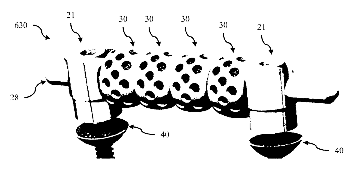
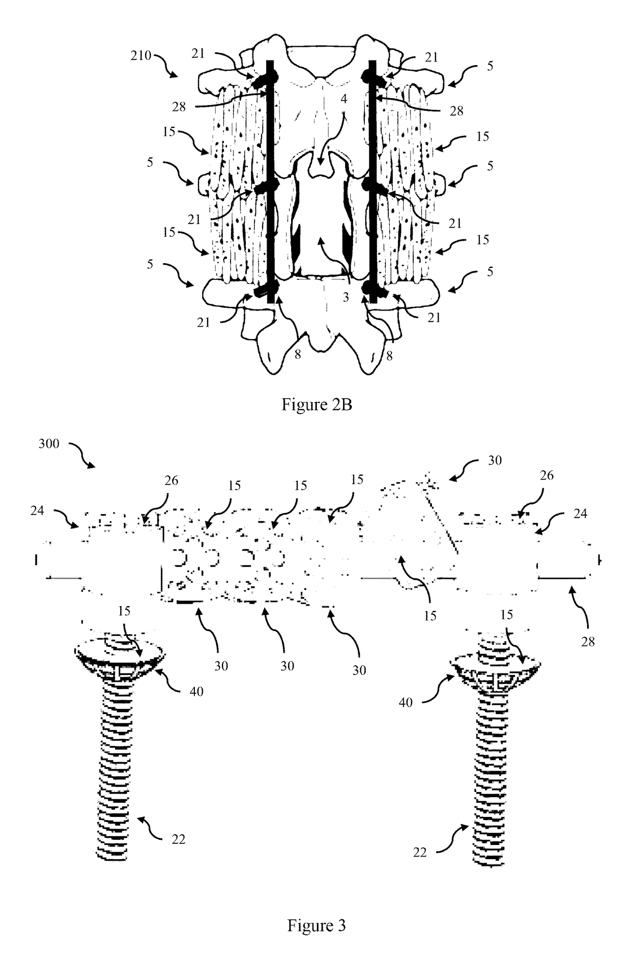
[0078]A major challenge for MIS posterolateral spinal fusion is delivering bone graft material adjacent to the rod and pedicle screws where there is limited access and the area is surrounded by muscle and connective tissue. Various embodiments of bone graft scaffold arrangements will now be described that can be used in MIS posterolateral spinal fusion, along with other orthopaedic surgical procedures including open posterolateral spinal fusion and interbody spinal fusion, or to assist in delivering bone graft material along a desired path or specific region. Embodiments of the bone graft scaffold apparatus comprise a housing which comprises a cavity for receiving bone growth promoting materials and a plurality of apertures. In use these allow bone growth material to move out into the surrounding tissue (eg by leaking or leaching out, or via mechanical or compressive forces forcing material out of the cavity) and / or bone (and blood vessels) to grow through the plurality of apertures...


PUM


Abstract

Bone graft scaffold arrangements are described that can be used in minimally invasive posterolateral spinal fusion. The bone graft scaffold apparatus comprise a housing which comprises a cavity for receiving bone growth promoting materials and a plurality of apertures. In use these allow bone and blood vessels to grow through the plurality of apertures to form the bone bridge between vertebrae. Further the bone graft scaffold apparatus comprise at least one opening in the housing for receiving a shaft of an orthopaedic device, such as rod linking pedicle screws, or the shaft of a pedicle screw, or another suitable shaft in another surgical procedure. The apparatus can be attached to structural components such as rods and screws and used to form a continuous scaffold between vertebras to assist in forming a bone bridge.

Description

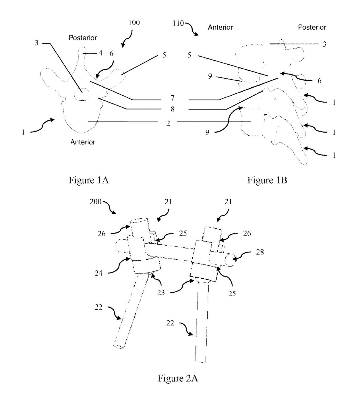
PRIORITY DOCUMENTS[0001]The present application claims priority from Australian Provisional Patent Application No. AU2014904026 titled “Bone Scaffold Improvements” and filed on 9 Oct. 2014, the content of which is hereby incorporated by reference in its entirety.TECHNICAL FIELD[0002]The present disclosure relates to orthopaedic devices. In a particular form the present disclosure relates to orthopaedic devices for minimally invasive posterolateral spinal fusion procedures.BACKGROUND[0003]Spinal fusion surgical procedures involve rigidly fixing two or more vertebrae together in order to alleviate back pain or correct spinal malalignments or degenerative conditions. FIG. 1A shows a top or superior view 10 of a vertebra 1 comprising a body 2, the spinal cord 3, spinous process 4, transverse process 5 and vertebral arch 6 comprising lamina 7 and pedicle 8. FIG. 1B further shows a left posterolateral view 11 of articulated vertebrae 1 each separated by intervertebral disc 9. Spinal fusio...

Claims


Application Information

Patent Timeline
Patent Type & Authority Applications(United States)
IPC IPC(8): A61F2/44A61B17/70A61B17/86A61F2/30A61B17/00A61F2/28
CPCA61F2/4455A61B17/8695A61B17/7002A61F2/30771A61F2/30734A61B17/7032A61F2002/2835A61F2002/3068A61F2002/30622A61F2002/30787A61F2002/3093A61B2017/00915A61B17/7035A61B17/1635A61B17/7098A61B17/68A61B17/842A61F2002/30224A61F2002/30227A61F2002/30233
Inventor PEDOULIAS, PANAGIOTISMCDONALD, MATTHEW JAMESHILL, NATHAN CHRISTOPHER
Owner PEDOULIAS PANAGIOTIS DR
Learn More