
Fuel tank cap capable of capturing harmful vapors

a fuel tank and vapor cap technology, applied in the direction of separation processes, transportation and packaging, packaging, etc., can solve the problems of gas flow, fuel tank explosion, harmful vapors generated in the fuel tank, etc., and achieve the effect of balancing the pressure between the fuel tank and the atmospher

Active Publication Date: 2017-10-26
SENTEC E&E CO LTD
View PDF0 Cites 4 Cited by
  • Summary
  • Abstract
  • Description
  • Claims
  • Application Information

AI Technical Summary

Benefits of technology

The invention provides a fuel tank cap that improves capturing harmful fuel vapor molecules with activated carbon without increasing the size and cost of the cap. The design includes concentric troughs for activated carbon that are easy to replenish, and the activated carbon is placed between a sealing disc and a non-woven member to hold it in place. The design also allows for a smooth passage of fuel vapor molecules through the activated carbon, making it more efficient. Additionally, the design includes a vapor vent channel that balances pressure in the fuel tank and the atmosphere, while absorbing harmful molecules with the activated carbon, resulting in a release of harmless fuel vapor molecules into the atmosphere without polluting the air.

Problems solved by technology

VOCs in fuel vapors generated in a fuel tank are harmful when breathing into the body.
Otherwise, the fuel tank may explode if the expansion pressure exceeds the maximum value or the gas flow from the fuel tank to the engine is greatly adversely affected if the contraction pressure exceeds the maximum value.
However, there are many dead ends in the conventional activated carbon canister in the vapor vent channel and in turn it may adversely affect harmful vapors absorption by the activated carbon.
However, it has disadvantages including increasing the size and the manufacturing cost of the fuel tank cap, complicating the construction of the fuel tank cap, lowering convenience in use, and making the product less practicable.

Method used


Image

  • Fuel tank cap capable of capturing harmful vapors
  • Fuel tank cap capable of capturing harmful vapors
  • Fuel tank cap capable of capturing harmful vapors

Examples


Embodiment Construction

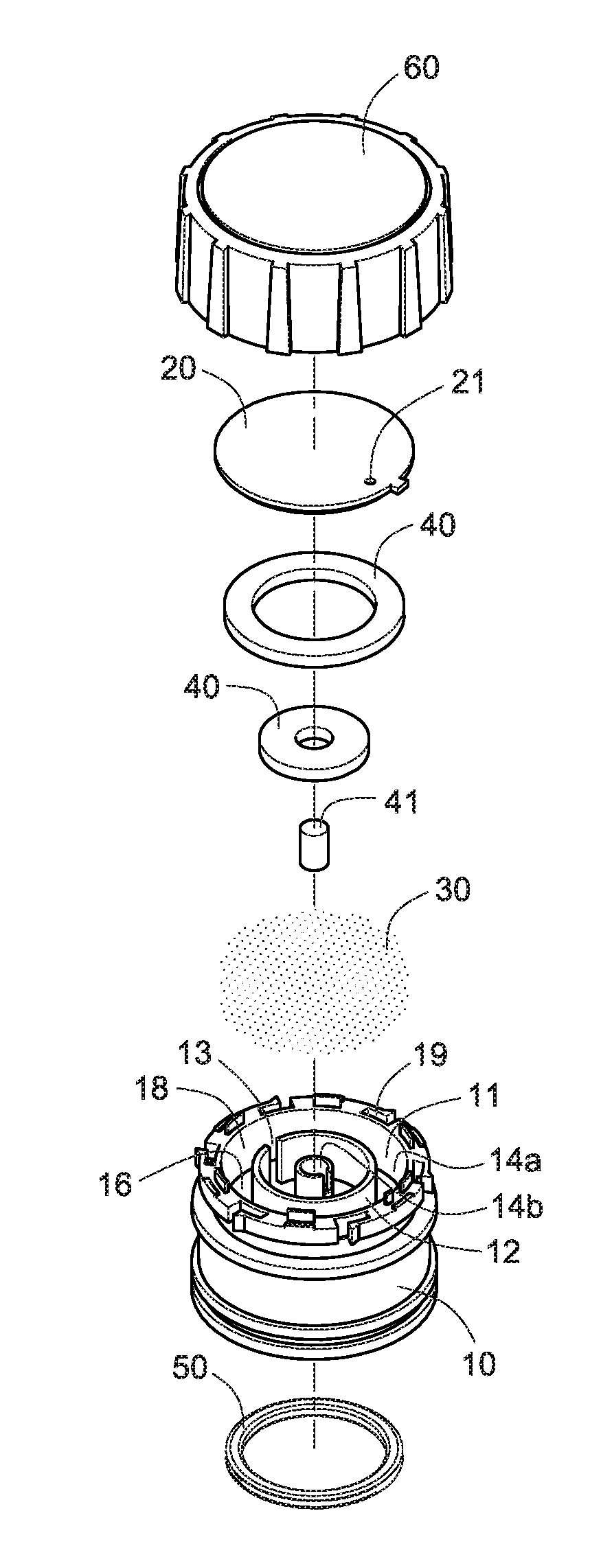
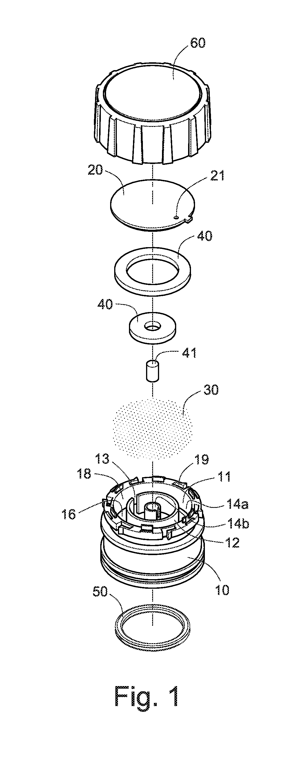
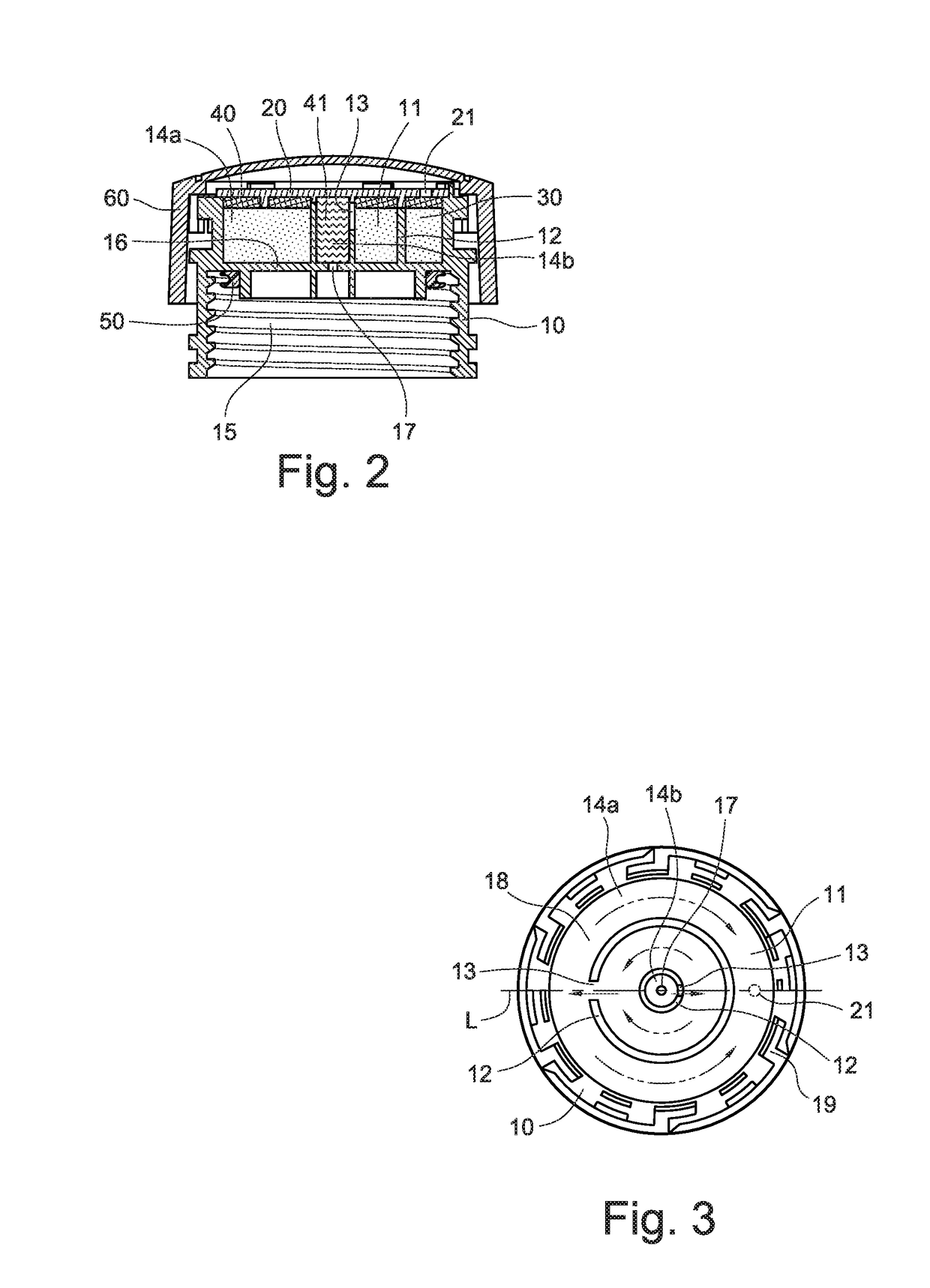
[0025]Referring to FIGS. 1 to 5, a fuel tank cap in accordance with the invention comprises the following components as discussed in detail below.

[0026]A casing 10 includes a main chamber 11 and a vapor vent channel 18 in the main chamber 11. The casing 10 is implemented as a cap secured to the opening of a fuel tank of an automobile formed by injection molding. A divider 16 is formed in the casing 10 to divide the casing 10 into the main chamber 11 and a lower chamber 15. A passageway 17 is formed through a center of the divider 16 for communicating the main chamber 11 with the lower chamber 15. A sealing disc 20 is releasably secured onto a top of the casing 10 to seal the main chamber 11. The sealing disc 20 has a through hole 21 for communicating the main chamber 11 with the atmosphere. The lower chamber 15 has internal threads for securing to the externally threaded opening of the fuel tank of an automobile. An O-ring 50 is put on an inner structure of the lower chamber 15 as a...


PUM

PropertyMeasurementUnit
flexibleaaaaaaaaaa
transparentaaaaaaaaaa
pressureaaaaaaaaaa

Abstract

A fuel tank cap includes a casing; a main chamber disposed in the casing; a vapor vent channel disposed in the casing and communicating with the main chamber; annular partition walls disposed in the main chamber and configured to divide the main chamber into troughs surrounding a central tunnel, each partition wall including a cut so that the troughs and the tunnel are capable of communicating with each other via the cut; activated carbon filled in the troughs; and a permeable plug disposed in the tunnel, which is made by wrapping rust-resistant flexible wires so that a plurality of intercommunicated air gaps are formed among the flexible wires. The vapor vent channel includes the cuts, the troughs and the air gaps. The activated carbon captures fuel vapors and absorbs VOCs in the fuel vapors when the fuel vapors pass through the vapor vent channel.

Description

RELATED ARTS[0001]This application is a continuation-in-part of U.S. patent application Ser. No. 15 / 137,784, filed on Apr. 25, 2016.BACKGROUND OF THE INVENTION1. Technical Field[0002]The invention relates to devices for capturing harmful volatile organic compounds (VOCs) in fuel vapors and more particularly to a fuel tank cap capable of capturing harmful VOCs in fuel vapors generated in a fuel tank of an automobile.2. Related Art[0003]Extracted hydrocarbons in a liquid form are referred to as petroleum. Gasoline is a transparent, petroleum-derived liquid that is used primarily as a fuel in internal combustion engines of, for example, automobiles. VOCs in fuel vapors generated in a fuel tank are harmful when breathing into the body. Thus, it is important to recover or capture the harmful vapor prior to releasing into the atmosphere.[0004]Fuel tank system of an automobile is used to store gas. The fuel tank system consists of an independent fuel tank and a fuel tank attached to an eng...

Claims


Application Information

Patent Timeline
Patent Type & Authority Applications(United States)
IPC IPC(8): B01D53/04B60K15/04B60K15/035
CPCB01D53/0407B60K15/0406B01D2259/4516B01D2253/102B01D2257/708B60K15/035B60K15/03504B60K2015/03514B60K2015/03547B60K2015/03585B60K2015/0438B60K2015/0451Y02A50/20
Inventor CHOU, CHUN-CHIYU, CHIA-MING
Owner SENTEC E&E CO LTD
Learn More