
Pneumatic Tire and Vehicle

a technology applied in the field of pneumatic tires and vehicles, can solve the problems of significant the reliability of estimation results may decline, and the decline in so as to prevent collisions between vehicles, suppress the decline of the recognition rate of vehicles by cameras, and high recognition rate

Inactive Publication Date: 2017-10-26
YOKOHAMA RUBBER CO LTD
View PDF15 Cites 20 Cited by
  • Summary
  • Abstract
  • Description
  • Claims
  • Application Information

AI Technical Summary

Benefits of technology

The patent is about a technology that helps avoid collisions between vehicles by understanding their speed and the information about their tires. The technology uses a camera to capture images and a system analyzes the images to estimate the speed of the vehicle and the information about the tires. This technology prevents declines in the recognition rate of vehicles and prevents collisions between vehicles. Overall, this patent aims to provide a safer driving experience for drivers.

Problems solved by technology

With systems in which cameras are used, the recognition rate of the vehicle by the camera may decline when it rains.
If the distance between the vehicles is estimated on the basis of an image of the tail lamps projected on the road surface instead of on the basis of an actual image of the tail lamps, the reliability of the estimation results may decline.
Particularly, when it rains at night, the recognition rate of the vehicle by the camera may decline significantly.
As such, the colored region will last a long time.
When the wear state of the tread portion is great, the vehicle itself on which the pneumatic tire is mounted has a greater possibility of having a longer braking distance, or slipping.
For example, in cases where a long period of time has passed since the tire manufacturing date, the vehicle itself has a high possibility that the performance of the pneumatic tire has deteriorated, and the vehicle itself has a high possibility of having problems stably traveling.
Additionally, in cases where the vehicle itself is traveling at the maximum traveling speed of the pneumatic tire or faster, the vehicle itself has a high possibility of having problems stably traveling.
For example, in cases where summer tires are mounted on the vehicle itself even though it is winter, the vehicle itself has a high possibility of having problems stably traveling.
In cases where a pneumatic tire with low grip performance is mounted on the vehicle itself even though it is raining, the vehicle itself has a high possibility of having problems stably traveling.
For example, in cases where vehicle weight is great, the vehicle itself has a high possibility of having a longer braking distance.
As such, the colored regions will last a long time.

Method used


Image

  • Pneumatic Tire and Vehicle
  • Pneumatic Tire and Vehicle
  • Pneumatic Tire and Vehicle

Examples


first embodiment

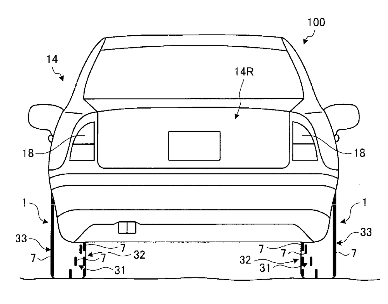
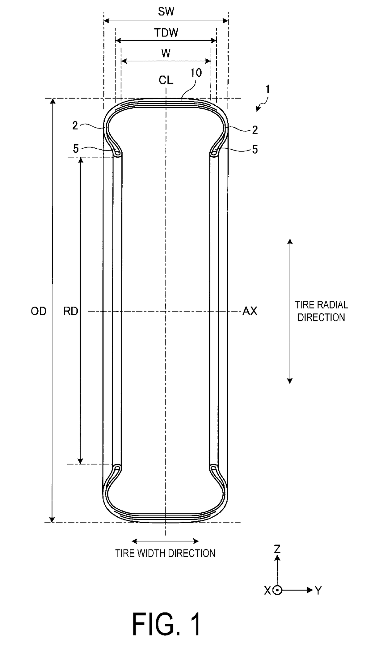
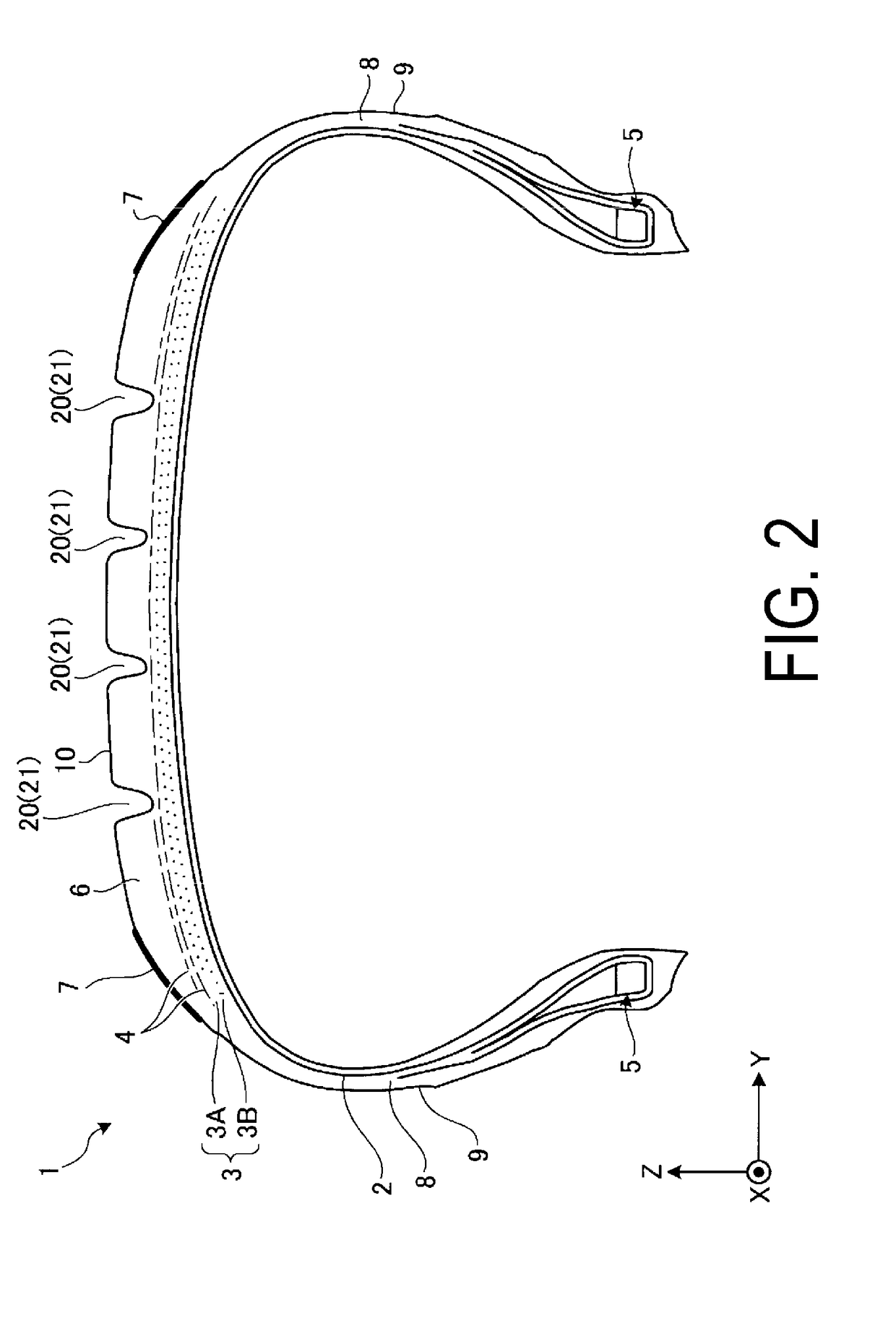
[0081]A first embodiment will be described. FIG. 1 is a cross-sectional view illustrating an example of a pneumatic tire 1 according to the present embodiment. FIG. 2 is an enlarged cross-sectional view of a portion of the pneumatic tire 1 according to the present embodiment. In the description below, the pneumatic tire 1 is also referred to as tire 1 for convenience.

[0082]The tire 1 is capable of rotation about a center axis (rotation axis) AX. FIGS. 1 and 2 each illustrate a meridian cross-section taken through the center axis AX of the tire 1. The center axis AX of the tire 1 is orthogonal to an equatorial plane CL of the tire 1.

[0083]In the present embodiment, the center axis AX of the tire 1 is parallel to the Y axis. That is, in the present embodiment, a direction parallel to the center axis AX is the Y-axis direction. The Y-axis direction is a vehicle width direction or a width direction of the tire 1. The equatorial plane CL passes through the center in the Y-axis direction ...

second embodiment

[0143]Next, a second embodiment will be described. In the description below, identical or substantially similar constituent portions to those of the above-described embodiments are assigned with the same reference numbers, and descriptions of those constituent portions are either simplified or omitted.

[0144]FIG. 8 is a drawing illustrating an example of a tire 1 according to the present embodiment. As illustrated in FIG. 8, the colored region 7 may be provided on the inner surface of the main groove 21. Note that the colored region 7 may be provided on all of the plurality of main grooves 21 (four in this example), or may be provided on a portion (e.g. two) of the main grooves 21.

[0145]The inner surface of the main groove 21 includes a bottom surface 21A, a first wall surface 21B disposed on a first side of the bottom surface 21A in the Y-axis direction, and a second wall surface 21C disposed on a second side of the bottom surface 21A. In the present embodiment, an angle θ formed by...

third embodiment

[0148]Next, a third embodiment will be described. In the description below, identical or substantially similar constituent portions to those of the above-described embodiments are assigned with the same reference numbers, and descriptions of those constituent portions are either simplified or omitted.

[0149]FIG. 9 is a drawing illustrating an example of a tire 1 according to the present embodiment. As illustrated in FIG. 9, in the present embodiment, the colored region 7 is provided on the surface between the +Y side ground contact edge portion 60 of the ground contact region of the tread portion 10 and the farthest portion 80 to the +Y side of the sidewall portion 9 disposed on the +Y side of the tread portion 10. The ground contact edge portion 60 is the edge portion of the tread ground contact width W. The portion 80 is the edge portion of the total tire width SW.

[0150]Note that in the example illustrated in FIG. 9, the colored region 7 is disposed on a first side (the +Y side) of...


PUM

PropertyMeasurementUnit
Angleaaaaaaaaaa
Angleaaaaaaaaaa
Lengthaaaaaaaaaa

Abstract

A pneumatic tire includes a surface and is rotatable about a center axis. The surface of the pneumatic tire includes a ground colored region including a surface of rubber, and an image recognition belt region including a colored region provided in a circumferential direction of the center axis.

Description

TECHNICAL FIELD[0001]The present technology relates to a pneumatic tire and a vehicle.BACKGROUND ART[0002]In the technical field of automobiles, collision avoidance systems that detect the distance between a leading vehicle and a following vehicle and prevent collisions between the vehicles have been put into practical use. Systems using millimeter wave sensors, systems using radar sensors, and systems using cameras are known as systems for detecting the distance between vehicles. U.S. Pat. No. 8,164,628 and Japanese Unexamined Patent Application Publication No. 2013-101040A describe technologies for estimating the distance between a leading vehicle and a following vehicle using an image acquired by a camera. U.S. Pat. No. 8,164,628 describes a technology for estimating the distance to a leading vehicle using a series of images recorded by a monocular camera. Japanese Unexamined Patent Application Publication No. 2013-101040A describes a technology for extracting the left and right ...

Claims


Application Information

Patent Timeline
IPC IPC(8): G06K9/00B60C9/18B60C11/03C08K5/00C08K3/00
CPCG06K9/00637B60C9/18B60C2009/1828C08K3/0033C08K5/0041B60C11/03B60C11/00B60C13/00B60C5/00B60C11/0306B60C13/001B60C11/0041B60C11/01B60C11/24B60C11/0008B60C11/1307C08K3/013G06V20/176
Inventor TANNO, ATSUSHI
Owner YOKOHAMA RUBBER CO LTD
Learn More