Integrated module having antenna

a module and integrated technology, applied in the field of antennas, can solve the problems of complex way of assembling wires from the co-axial cable b>3/b> and the co-axial cable b>1/b> to the wireless module, and the design may be severe,

Active Publication Date: 2017-10-26
CHANGSHU HONGBO TELECOMM TECH CO LTD
View PDF4 Cites 2 Cited by
  • Summary
  • Abstract
  • Description
  • Claims
  • Application Information

AI Technical Summary

Benefits of technology

[0007]Further, the trend of the design of the laptop or the terminal device is to reduce the non-necessary volume and to remove the non-necessary component to reduce the weight. On the contrary, the bandwidth provided by the antenna needs to be larger to meet the application of high-speed transmission or a variety of broadband application. Hence, in the condition that the space in a laptop for an antenna is narrower and more bandwidth is needed, the manufacturer needs to modify the structure of the antenna 2a and the antenna 2b to meet the specification when the antenna is applied in different laptop. Therefore, it is expectable that the antenna for different laptop is different in convention, and the manufacturer needs to make the specified antenna structure for each type of laptop. Different embedded antenna structure is needed for different laptop, and the cost of manufacture is difficult to be reduced.

Problems solved by technology

However, the attenuation of the design may be severe because the length of each of the co-axial cables 3a and 3b.
Further, the way of assembling the wires from the co-axial cable 3a and the co-axial cable 3b to the wireless module 1 is complicated.
However, the installation of the antenna in FIG. 2 results in bad radiation pattern and the antenna suffers from the interference.
Further, the specific absorption rate (SAR) according to safety specifications is also a problem to be considered.
Then, according to the design in FIG. 3, the antennas 2a and 2b are disposed on the two lateral surface of the keyboard, so it suffers from more interference compared with the aforementioned designs and its efficiency of the antenna is worse.
The installation makes the antenna suffer from more noise interference and have worse efficiency compared with the aforementioned designs.
Different embedded antenna structure is needed for different laptop, and the cost of manufacture is difficult to be reduced.

Method used


Image

  • Integrated module having antenna
  • Integrated module having antenna
  • Integrated module having antenna

Examples


Embodiment Construction

[0023]In the following detailed description, for purposes of explanation, numerous specific details are set forth in order to provide a thorough understanding of the disclosed embodiments. It will be apparent, however, that one or more embodiments may be practiced without these specific details. In other instances, well-known structures and devices are schematically shown in order to simplify the drawings.

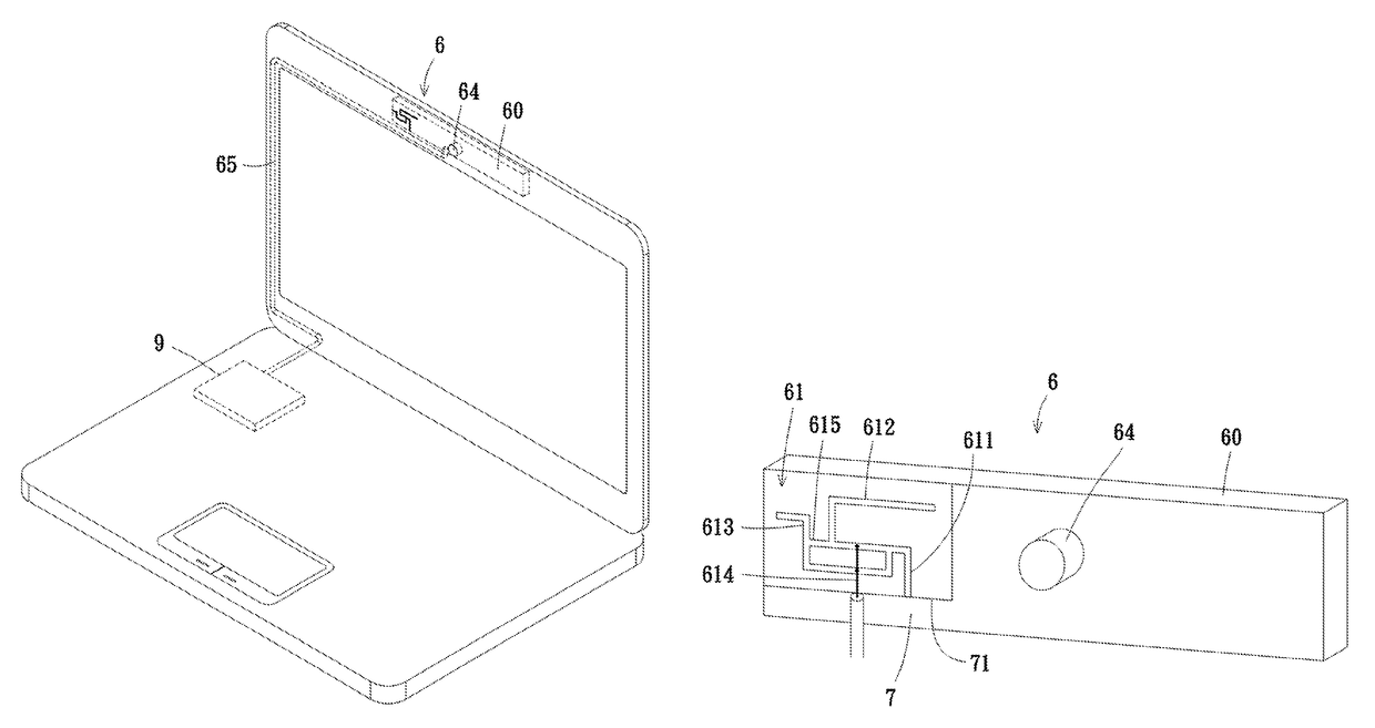
[0024]Please refer to FIG. 5A, which is a schematic of an integrated module having an antenna disposed on the upper side of the screen of the laptop in one embodiment of the disclosure. The integrated module having an antenna 6 is installed in the casing of the laptop, and only the camera of the camera module 64 is exposed on the casing. Explicitly, the integrated module having an antenna 6 includes a module substrate 60, a camera module 64 and a first antenna 61. The camera module 64 is disposed on the module substrate 60 and has a camera. The first antenna 61 is disposed on the m...


PUM


Abstract

An integrated module having an antenna comprises a module substrate, a camera module and the antenna disposed on the module substrate. The antenna comprises a grounding portion connected to ground plane, a low-frequency radiating arm, a high-frequency radiating arm, a feed-in line and a shorting portion. A connection portion of the low-frequency radiating arm and a connection portion of the high-frequency radiating arm are connected to the grounding portion. A free-end portion of the high-frequency radiating arm and a free-end portion of the low-frequency radiating arm are back-to-back and extend towards opposite directions. The feed-in line is perpendicular to an edge of the ground plane and extends away from the ground plane. The feed-in line crosses and connects the high-frequency radiating arm to provide a second feeding-point. The end of the feed-in line is connected to the connection portion of the low-frequency radiating arm to provide a first feeding-point.

Description

CROSS-REFERENCE TO RELATED APPLICATIONS[0001]This non-provisional application claims priority under 35 U.S.C. §119(a) on Patent Application No(s). 105112884 filed in Taiwan (R.O.C.) on Apr. 26, 2016, the entire contents of which are hereby incorporated by reference.BACKGROUNDTechnical Field[0002]The disclosure relates to an antenna, and more particularly to an integrated module having an antenna.Related Art[0003]Please refer to FIG. 1 through FIG. 4. Conventionally, the embedded antenna designs for electronic device such as laptop may be categorized into the following types according to the location for disposing the antenna. In the design of FIG. 1, one or more antennas 2a and 2b are disposed at the upper edge of the screen of the laptop so as to achieve a good radiation pattern with less interference of noise for the simple surrounding of the antenna. Here, the antenna 2a and the antenna 2b are connected to the wireless module 1 via the co-axial cable 3a and co-axial cable 3b, res...

Claims


Application Information

Patent Timeline
Patent Type & Authority Applications(United States)
IPC IPC(8): H01Q1/22H01Q9/04H01Q1/48
CPCH01Q1/2266H01Q9/0421H01Q1/48H01Q1/44H01Q5/35H01Q5/371H01Q7/00H01Q9/42H01Q21/28H01Q21/29
Inventor SHIH, YU-LINLEE, KUAN-WEICHANG, YAO-YUANCHIU, TSUNG-WEN
Owner CHANGSHU HONGBO TELECOMM TECH CO LTD
Why Eureka
Try Eureka