Reticle processing system

Active Publication Date: 2017-11-02
VARIAN SEMICON EQUIP ASSOC INC
View PDF1 Cites 1 Cited by
  • Summary
  • Abstract
  • Description
  • Claims
  • Application Information

AI Technical Summary

Benefits of technology

[0005]In view of the foregoing, an advantage of the present disclosure is to provide a customized support assembly including a plate coupled to a frame, the plate including a plurality of pins extending from the plate through corresponding openings in a carrier base of a carrier assembly

Problems solved by technology

However, this approach is undesirable because multiple lifting and clamping components are provided near the reticle, thus increasing the possibility particles are generated.
Furthermore, current techniques undesirably place the reticle in an enclosure, as opposed to directly in a cle

Method used


Image

  • Reticle processing system
  • Reticle processing system
  • Reticle processing system

Examples


Example

[0019]The drawings are not necessarily to scale. The drawings are merely representations, not intended to portray specific parameters of the disclosure. Furthermore, the drawings are intended to depict exemplary embodiments of the disclosure, and therefore is not considered as limiting in scope.

[0020]Furthermore, certain elements in some of the figures may be omitted, or illustrated not-to-scale, for illustrative clarity. The cross-sectional views may be in the form of “slices”, or “near-sighted” cross-sectional views, omitting certain background lines otherwise visible in a “true” cross-sectional view, for illustrative clarity. Furthermore, for clarity, some reference numbers may be omitted in certain drawings.

DETAILED DESCRIPTION

[0021]Various approaches in accordance with the present disclosure will now be described more fully hereinafter with reference to the accompanying drawings, where embodiments of the methods are shown. The approaches may be embodied in many different forms ...


PUM


Abstract

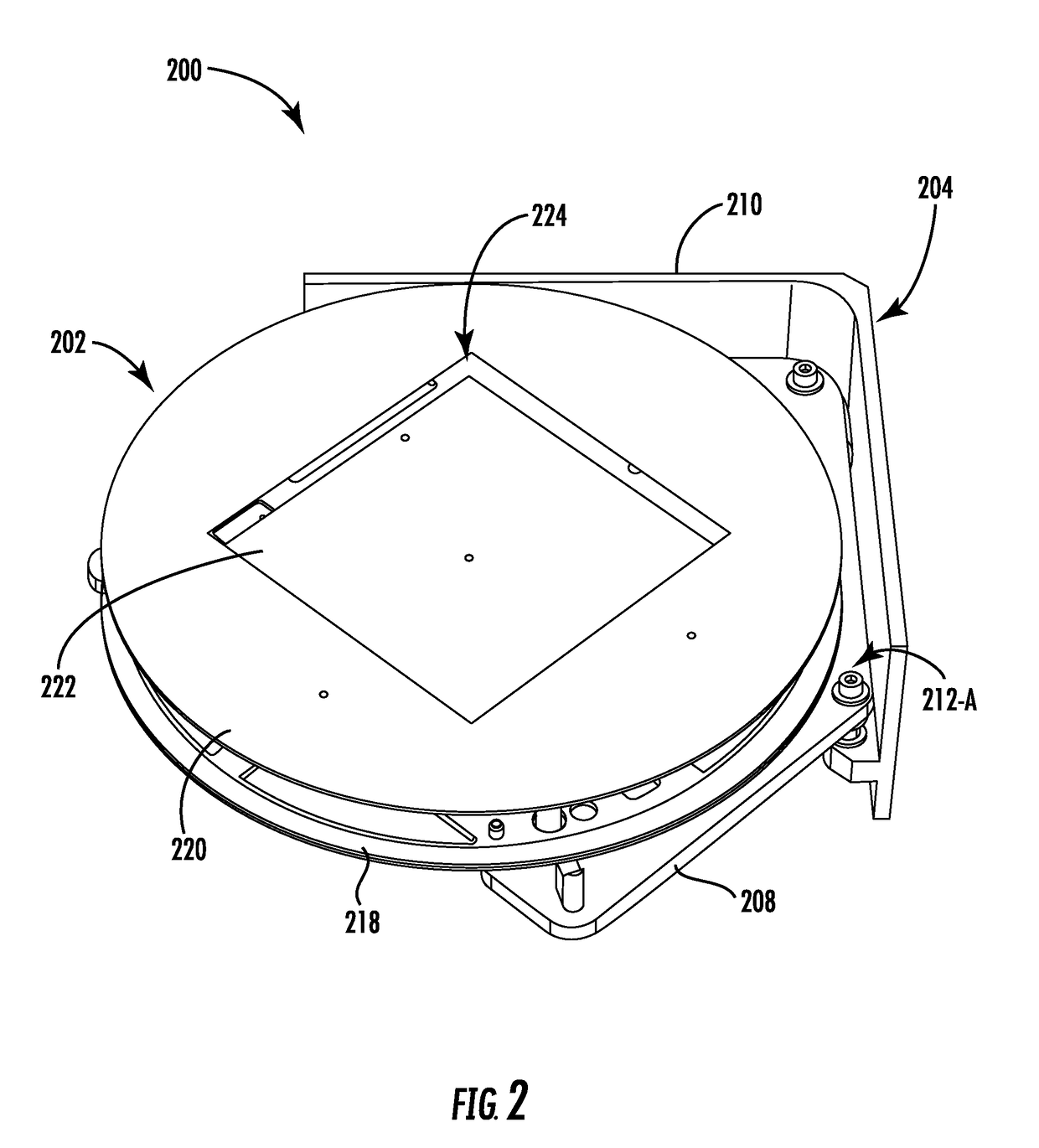
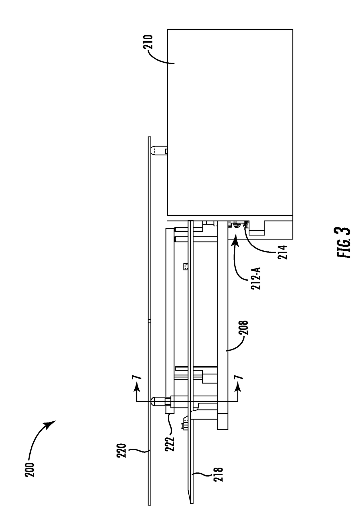
Provided herein are approaches for processing reticle blanks. In one approach, a reticle processing system includes a support assembly having a plate coupled to a frame, and a carrier assembly coupled to the support assembly. In one approach, the carrier assembly includes a carrier base coupled to the plate, a reticle disposed over the carrier base, and a carrier shield disposed over the reticle, wherein the carrier shield may include a central opening formed therein, allowing for placement and extraction of the reticle. In one approach, when the carrier assembly is placed atop the support assembly, a plurality of pins extend from the plate through corresponding openings in the carrier base, the plurality of pins supporting the carrier assembly so the carrier base, the reticle, and the carrier shield are each independently supported and vertically separated from one another.

Description

FIELD OF THE DISCLOSURE[0001]Embodiments of the present disclosure relate generally to lithography reticle blank processing and, more specifically, to a customized support assembly and associated method for processing lithography reticle blanks using the support assembly.BACKGROUND OF THE DISCLOSURE[0002]Extreme ultraviolet lithography (EUV), also known as soft x-ray projection lithography, has begun to replace deep ultraviolet lithography for the manufacture of 0.13 micron, and smaller, minimum feature size semiconductor devices. EUV systems operate by reflection instead of transmission of light. Through the use of a series of mirrors, or lens elements, and a reflective element, or mask blank, coated with a non-reflective absorber mask pattern, patterned actinic light is reflected onto a resist-coated semiconductor wafer.[0003]Conventional EUV blank processes may include, for example, a 152 mm×152 mm blank reticle being placed into a coating tool to apply various coatings. As confi...

Claims


Application Information

Patent Timeline
IPC IPC(8): G03F1/22
CPCG03F1/22H01L21/67259H01L21/67346H01L21/681H01L21/68707H01L21/68785G03F7/70716G03F9/7096
Inventor STRASSNER, JAMESCARLSON, CHARLESVOPAT, BRENTBLAHNIK, JEFFREY
Owner VARIAN SEMICON EQUIP ASSOC INC
Why Eureka
Try Eureka