

High efficiency light compatibility device
- Summary
- Abstract
- Description
- Claims
- Application Information
AI Technical Summary
Benefits of technology
Problems solved by technology
Method used
Image

Examples
first embodiment
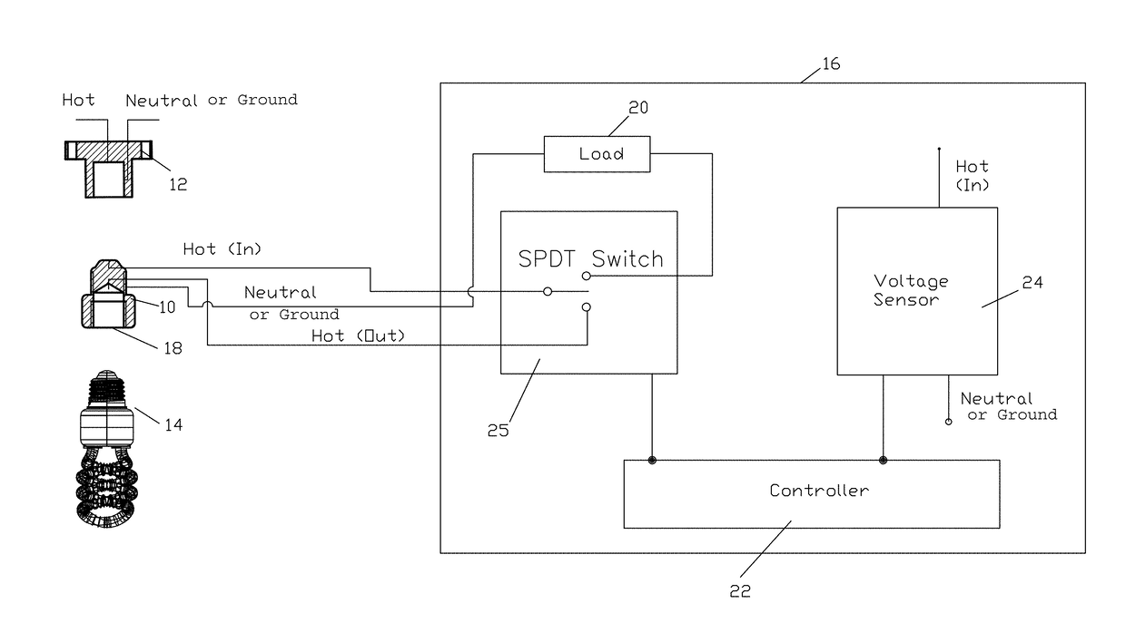
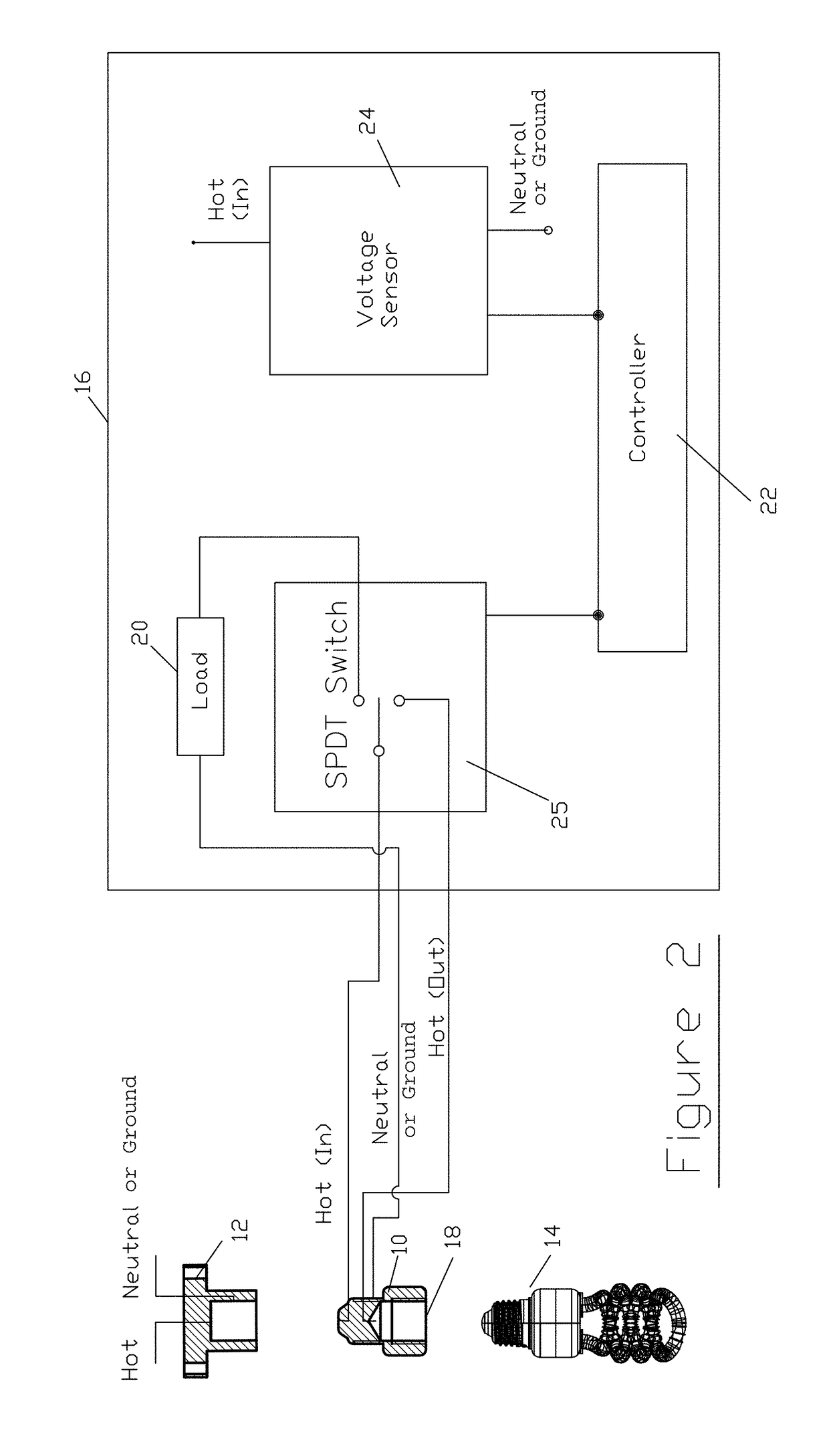
[0025]FIG. 2 illustrates a block diagram of anti-flicker or anti-glow apparatus 10 configured in accordance with the present invention. The apparatus 10 preferably is configured to be easily screwed into the original socket 12 of an electronically activated light source, such as an internal wall-mounted motion activated light switch using an energy efficient lamp 14, such as a CCFL or a CFL. The energy efficient lamp is simply screwed into the light socket 18 of the anti-flicker apparatus 10.
[0026]Block diagram 16 illustrates the internal electrical components of the anti-flicker apparatus 10 configured in accordance with a first embodiment of the present invention. Included in the anti-flicker apparatus 10 are a switchable load 20, a controller 22, a voltage sensor 24, and a switchable light source 23. In the illustrated embodiment, the switchable light source 25 is a Single-Pole Double-Through (SPDT) switch. The anti-flicker apparatus 10 is electrically connected between the light...
second embodiment
[0028]When the motion detector detects movement and switches to the “on” state, the voltage level across nodes Hot (A) and Neutral (or ground) (B) increases significantly, which is detected by the normally open “make before brake” relay 26. Sensing the increased voltage, the relay 26 switches to the closed position “C,” thus allowing current to flow through line 29 to the lamp 14, and then line 27 changes to an open connection. This design eliminates power loss across the resistor 28 during the “on” state. FIG. 4 is a block diagram of an anti-flicker or anti-glow switchable load apparatus 50 configured in accordance with the present invention. Illustrated is a motion detector 52 including a light socket 54 that is activated by the motion detector. The motion detector security light 52 is designed to be electrically connected and mounted to an electrical switch box for a light fixture having a “hot” wire connection 53 and a “neutral (or ground)” wire connection 55. The components of ...
PUM
 Abstract
Description
Claims
Application Information