
Fuel pump having improved pumping behavior

a fuel pump and pumping behavior technology, applied in the field of fuel pumps, can solve the problems of increasing frictional losses, increasing pressure drop, and significant drop in the delivery characteristic of fuel pumps, and achieve the effects of improving the delivery characteristic, uniform pressure drop, and reducing pressure drop

Active Publication Date: 2017-11-09
ROBERT BOSCH GMBH
View PDF2 Cites 5 Cited by
  • Summary
  • Abstract
  • Description
  • Claims
  • Application Information

AI Technical Summary

Benefits of technology

The invention is a fuel pump that has improved delivery characteristics, especially in hot fuel. It achieves this by reducing pressure drop and making the pressure drop in the piston chamber more uniform during the intake process. This results in a more consistent delivery characteristic regardless of the fuel temperature. The fuel pump includes a diaphragm seal element and a piston that seals with an inner and outer seal seat using equation to ensure equal flow rates. The diaphragm seal element has a central circular delivery opening for unobstructed delivery. The fuel pump also has a feed region that ensures a small stroke of the piston. The diaphragm seal element adheres to the piston during the opening process to maximize the cross-section area and achieve complete filling during the intake process.

Problems solved by technology

One set of problems with fuel pumps arises particularly in the case of hot fuel, when a pressure drop occurs during the intake process, with the result that gases are released from the hot fuel and the released gases can enter the delivery chamber of the fuel pump.
This can lead to a significant drop in the delivery characteristic of the fuel pump.
Moreover, the nonuniform pressure drop during the intake process can also lead to increased frictional losses, additionally intensifying the pressure drop.

Method used


Image

  • Fuel pump having improved pumping behavior
  • Fuel pump having improved pumping behavior
  • Fuel pump having improved pumping behavior

Examples


Embodiment Construction

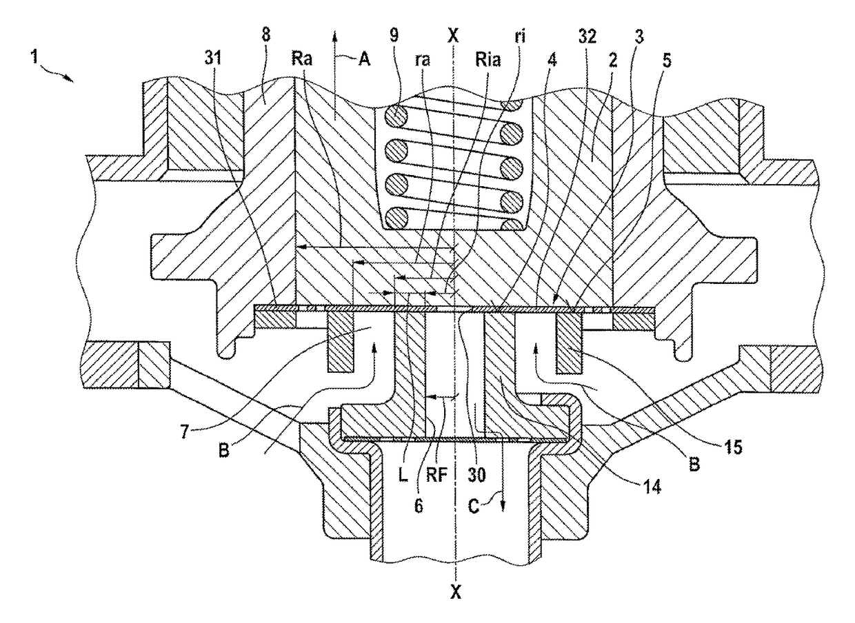
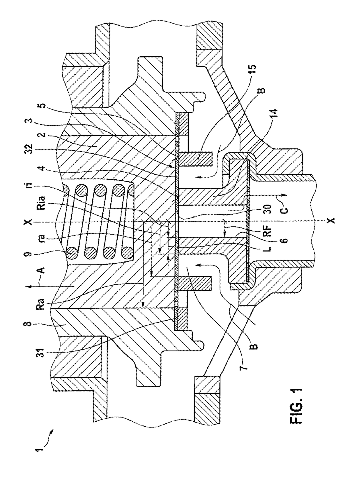
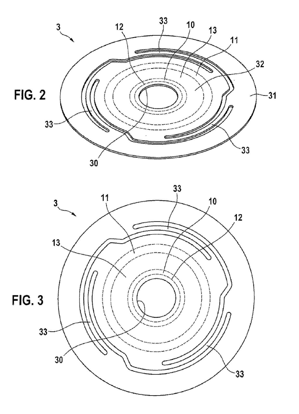
[0017]A fuel pump 1 according to a preferred illustrative embodiment of the invention is described in detail below with reference to FIGS. 1 to 3.

[0018]The fuel pump 1 comprises a piston 2, which can be moved backward and forward in a cylinder 8. Reference sign 9 denotes a return element, in this illustrative embodiment a cylindrical spring.

[0019]The fuel pump 1 furthermore comprises a diaphragm seal element 3, which is a disk-shaped element and is illustrated in detail in FIGS. 2 and 3. The diaphragm seal element 3 comprises a retaining region 31, which is formed in a ring shape at the outer circumference of the diaphragm seal element. The diaphragm seal element 3 furthermore comprises a sealing region 32, which is surrounded by the retaining region 31. Formed between the sealing region 32 and the retaining region 31 are three spring arms 33, which connect the retaining region 31 resiliently to the sealing region 32. A delivery opening 30 is furthermore formed centrally in the midd...


PUM


Abstract

The present invention relates to a fuel pump for pumping fuel, comprising a piston (2) and a diaphragm seal element (3), which seals on an inner annular seal seat (4) and an outer annular seal seat (5), wherein the following equation is satisfied: (Ra2−ra2) / (ri+L)2=ra / ri, where ri is the inner radius of the inner seal seat (4), ra is the inner radius of the outer seal seat (5), Ra is the outer diameter of the piston (2) and L is a difference between an outer radius (Ria) of the inner seal seat (4) and the inner radius (ri) of the inner seal seat (4). The invention further relates to a method for operating a fuel pump.

Description

BACKGROUND OF THE INVENTION[0001]The present invention relates to a fuel pump for delivering fuel, which has improved pumping behavior, especially in the case of hot fuel.[0002]Fuel pumps are known in various embodiments from the prior art. One set of problems with fuel pumps arises particularly in the case of hot fuel, when a pressure drop occurs during the intake process, with the result that gases are released from the hot fuel and the released gases can enter the delivery chamber of the fuel pump. This can lead to a significant drop in the delivery characteristic of the fuel pump. Moreover, the nonuniform pressure drop during the intake process can also lead to increased frictional losses, additionally intensifying the pressure drop.SUMMARY OF THE INVENTION[0003]In contrast, the fuel pump according to the invention has the advantage that an improved delivery characteristic is possible, especially in the case of hot fuel. In this case, according to the invention, a lower pressure...

Claims


Application Information

Patent Timeline
IPC IPC(8): F02M59/02F04B53/14F04B53/10
CPCF02M59/025F04B53/1032F04B53/143F02M51/04F02M59/464F02M63/0054F02M63/0077F02M69/02F02M2200/26F02M2200/04F02M37/04F04B53/1067
Inventor KRAUSE, ANDREASKORECK, JUERGENFLO, SIAMENDMAEURER, WALTER
Owner ROBERT BOSCH GMBH
Learn More