
Apparatus and method for energy management based on estimated resource utilization

Active Publication Date: 2017-11-09
ENEL X NORTH AMERICA INC
View PDF4 Cites 9 Cited by
  • Summary
  • Abstract
  • Description
  • Claims
  • Application Information

AI Technical Summary

Benefits of technology

The present invention provides a better way to determine the level of energy consumption in a building. It involves a network operations center (NOC) that generates schedules for controlling the use of energy by various devices in the building. These devices include sensors and control nodes that communicate with the NOC through an energy management network. The NOC adjusts the schedules based on real-time data from the sensors, ensuring efficient use of energy and optimal performance of the building. The invention allows for better management of energy consumption and can help reduce energy waste.

Problems solved by technology

One problem with resources such as electricity, water, fossil fuels, and their derivatives (e.g., natural gas) is related to supply and demand.
That is, production of a resource often is not in synchronization with demand for the resource.
In addition, the delivery and transport infrastructure for these resources is limited in that it cannot instantaneously match production levels to provide for constantly fluctuating consumption levels.
Another problem with resources such as water and fossil fuels (which are ubiquitously employed to produce electricity) is their limited supply along with the detrimental impacts (e.g., carbon emissions) of their use.
The answers to the above questions are not straightforward, primarily because, as one skilled in the art will appreciate, several factors both drive and often tend to obscure energy consumption.
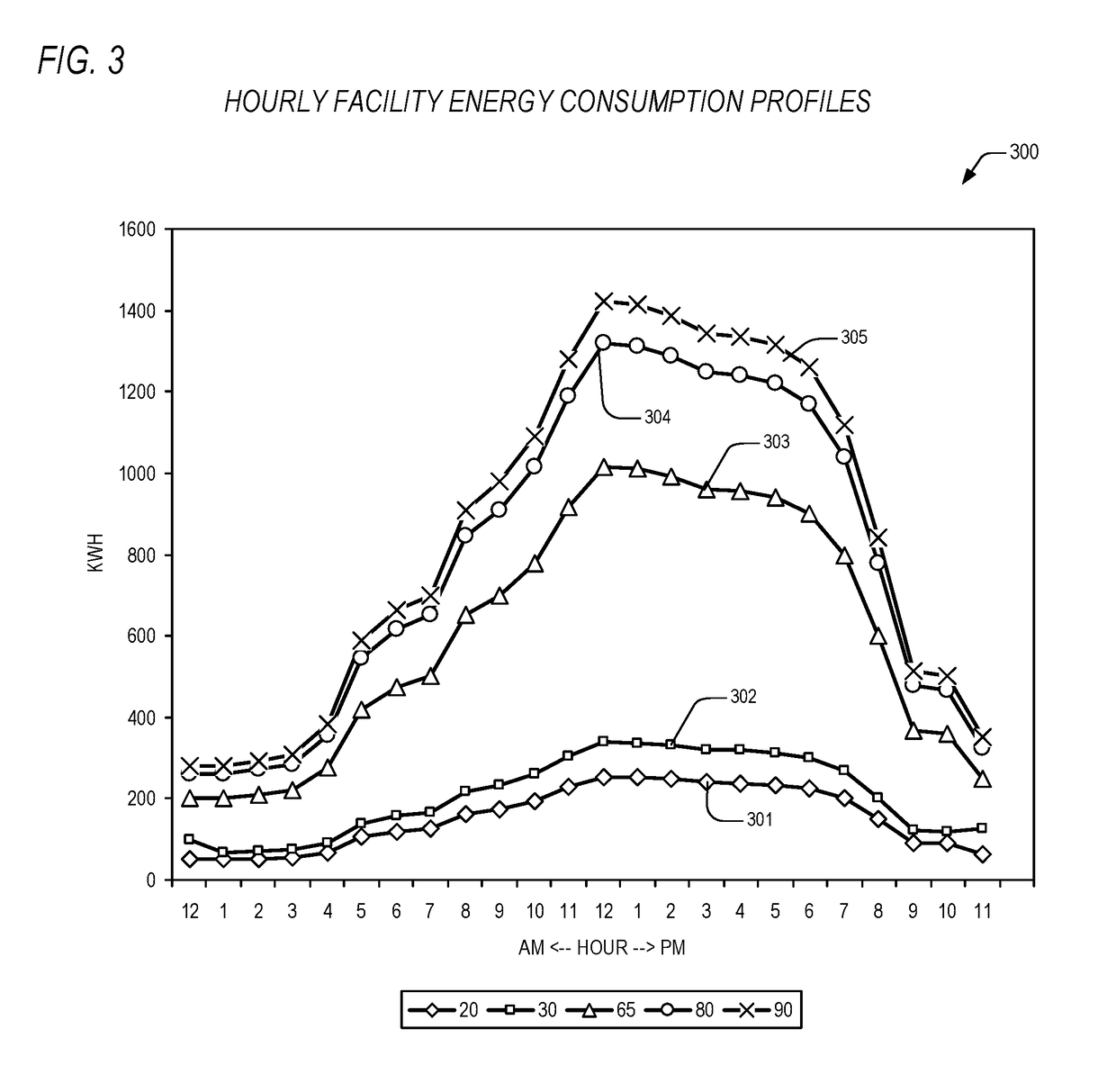
Weather conditions drive consumption, and their effects are significant.
Fortunately, those in the art have developed complex, but widely accepted, normalization techniques that provide for weather normalization of energy use data so that consumption by a building in two different months can be compared without the confusion associated with how outside temperature affects energy use.
The present inventors have observed, however, that another significant factor drives energy consumption, and also substantially complicates energy efficiency evaluations.
But, as one skilled in the art will appreciate, the effects of occupancy changes in the new year will significantly obscure the resulting comparison because more energy per student is consumed in the new year due to the increase in attendance.
The present inventors have observed that these techniques are disadvantageous and limiting in situations where occupancy need be determined in near real time on a daily basis, or where occupancy (or resource utilization) is to be estimated for a collocated number of facilities or a group of similar facilities.
That fact is that occupancy at an aggregated level is incredibly difficult to determine and predict, not only for comparative purposes, but also for purposes of real time control.

Method used


Image

  • Apparatus and method for energy management based on estimated resource utilization
  • Apparatus and method for energy management based on estimated resource utilization
  • Apparatus and method for energy management based on estimated resource utilization

Examples


Embodiment Construction

[0038]Exemplary and illustrative embodiments of the invention are described below. In the interest of clarity, not all features of an actual implementation are described in this specification, for those skilled in the art will appreciate that in the development of any such actual embodiment, numerous implementation specific decisions are made to achieve specific goals, such as compliance with system-related and business related constraints, which vary from one implementation to another. Furthermore, it will be appreciated that such a development effort might be complex and time-consuming, but would nevertheless be a routine undertaking for those of ordinary skill in the art having the benefit of this disclosure. Various modifications to the preferred embodiment will be apparent to those skilled in the art, and the general principles defined herein may be applied to other embodiments. Therefore, the present invention is not intended to be limited to the particular embodiments shown a...


PUM


Abstract

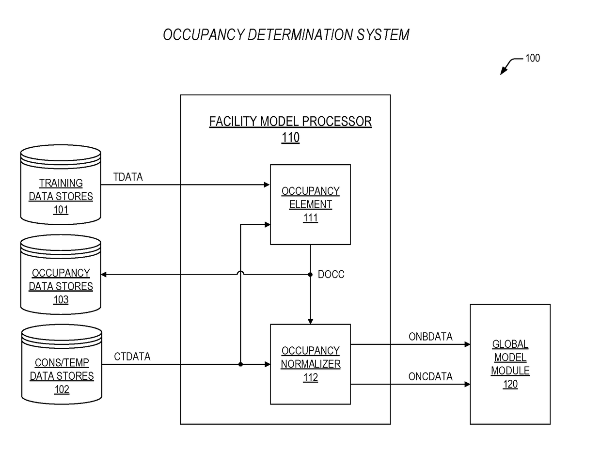
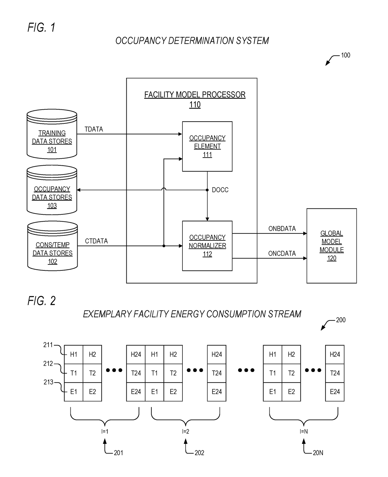
An apparatus for controlling consumption of an energy resource by a facility is provided. The apparatus includes a plurality of devices, a network operations center (NOC), and a plurality of control nodes. The plurality of devices is disposed within the facility, each consuming a portion of the energy resource when turned on, and the each capable of performing a corresponding function to maintain a desired level of performance by cycling on and off. The NOC is disposed external to the facility, and is configured to generate a plurality of run time schedules, where the plurality of run time schedules coordinates run times for the each of the plurality of devices to control the consumption of the energy resource while maintaining corresponding local environments and the desired level of performance, and is configured to adjust the plurality of run time schedules based upon resource utilization components and resource utilization levels generated by the NOC, where the resource utilization components and the resource utilization levels are exclusively generated based on the consumption of the energy resource and outside temperature. The plurality of control nodes is disposed within the facility, each coupled to a corresponding one of the plurality of devices, where the plurality of control nodes is coupled together via an energy management network that is operatively coupled to the NOC, and where the plurality of control nodes transmits sensor data and device status to the NOC via the energy management network for generation of the plurality of run time schedules, and where the plurality of control nodes executes selected ones of the run time schedules to cycle the plurality of devices on and off.

Description

CROSS-REFERENCE TO RELATED APPLICATIONS[0001]This application is related to the following co-pending U.S. patent applications, each of which has a common assignee and common inventors.SERIALFILINGNUMBERDATETITLEAPPARATUS AND METHOD FOR OCCUPANCY(ENER.0136)    DETERMINATIONAPPARATUS AND METHOD FOR OCCUPANCY(ENER.0137)    BASED ENERGY CONSUMPTION MANAGEMENTAPPARATUS AND METHOD FOR AUTOMATED(ENER.0138)    BUILDING SECURITY BASED ON ESTIMATEDOCCUPANCYAPPARATUS AND METHOD FOR TRAFFIC(ENER.0140)    CONTROL BASED ON ESTIMATED BUILDINGOCCUPANCYAPPARATUS AND METHOD FOR TARGETED(ENER.0141)    MARKETING BASED ON ESTIMATED BUILDINGOCCUPANCYAPPARATUS AND METHOD FOR ENERGY(ENER.0142)    MANAGEMENT OF MULTIPLE FACILITIES AS AFUNCTION OF ESTIMATED OCCUPANCYAPPARATUS AND METHOD FOR OCCUPANCY(ENER.0143)    BASED DEMAND RESPONSE DISPATCHPRIORITIZATIONAPPARATUS AND METHOD FOR FOCUSED(ENER.0144)    MARKETING MESSAGING BASED ON ESTIMATEDBUILDING OCCUPANCYAPPARATUS AND METHOD FOR FORECASTING(ENER.0145)   ...

Claims


Application Information

Patent Timeline
IPC IPC(8): G05F1/66G05B13/04
CPCG05B13/04G05F1/66
Inventor AL-MOHSSEN, HUSAINMAIN, ELIZABETH J.BASSA, ANGELA S.
Owner ENEL X NORTH AMERICA INC
Learn More