
Apparatus and method for automatic characterization and configuration of an LED lighting system

Inactive Publication Date: 2016-10-27
FABRIQ
View PDF2 Cites 3 Cited by
  • Summary
  • Abstract
  • Description
  • Claims
  • Application Information

AI Technical Summary

Benefits of technology

The present invention provides a superior technique for automatically configuring an LED driver to drive an LED module. The apparatus includes an identification element and a driver / exciter module. The identification element exhibits a unique frequency response to excitation by excitation signals generated exclusively over a power signal and a return signal, which indicates one of a plurality of constant currents in a second range, one of a plurality of first voltages, and one of a plurality of maximum power levels in a third range. The driver / exciter module is coupled to the identification element via the power and return signals, and is configured to provide the plurality of constant currents, the plurality of first voltages, and a plurality of second voltages within the first range, at the plurality of maximum power levels within the third range over the power and return signals. This allows for a precise auto-configuration of the LED driver to match the operating characteristics of the LED module.

Problems solved by technology

The present inventors have observed that the sheer number of different types of LED modules, along with their corresponding LED drivers is disadvantageous from many perspectives, most notably stocking and installation.
This is another disadvantage in the art which has been noted by the present inventors, primarily because of the expense associated with manufacturing, stocking, maintaining and cataloging an increasing number of LED module / LED driver variants.
Present day programmable LED drivers, as alluded to above, are an improvement, but the spectrum of LED modules that these programmable drivers support is limited.
They are limited because configuration of the drivers is typically achieved via mechanical switches or non-volatile memory, which limits the number of different parameters and operating characteristics that a given LED driver can achieve.
Another disadvantage of present day LED lighting technologies is that programmable LED drivers must be stocked in their unconfigured state, and subsequently must be configured to match corresponding LED module drive requirements, either before shipping or during installation.
A further disadvantage is that when an LED module or LED driver fails during installation, the LED module or LED driver must be replaced by an equivalent LED module or LED driver, either from the same manufacturer, or one that that is equivalent in terms of operating characteristics.
As one skilled in the art will appreciate, if the operating characteristics of a substitute LED module or LED driver are slightly different from the failed LED module or LED driver, then premature failure of the newly installed LED module or LED driver can occur or, worse, fire hazard can ensue.

Method used


Image

  • Apparatus and method for automatic characterization and configuration of an LED lighting system
  • Apparatus and method for automatic characterization and configuration of an LED lighting system
  • Apparatus and method for automatic characterization and configuration of an LED lighting system

Examples


second embodiment

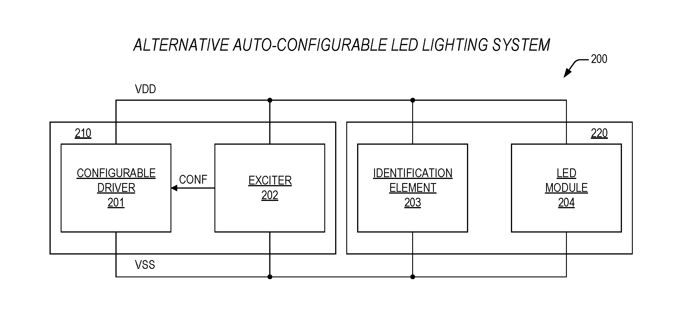
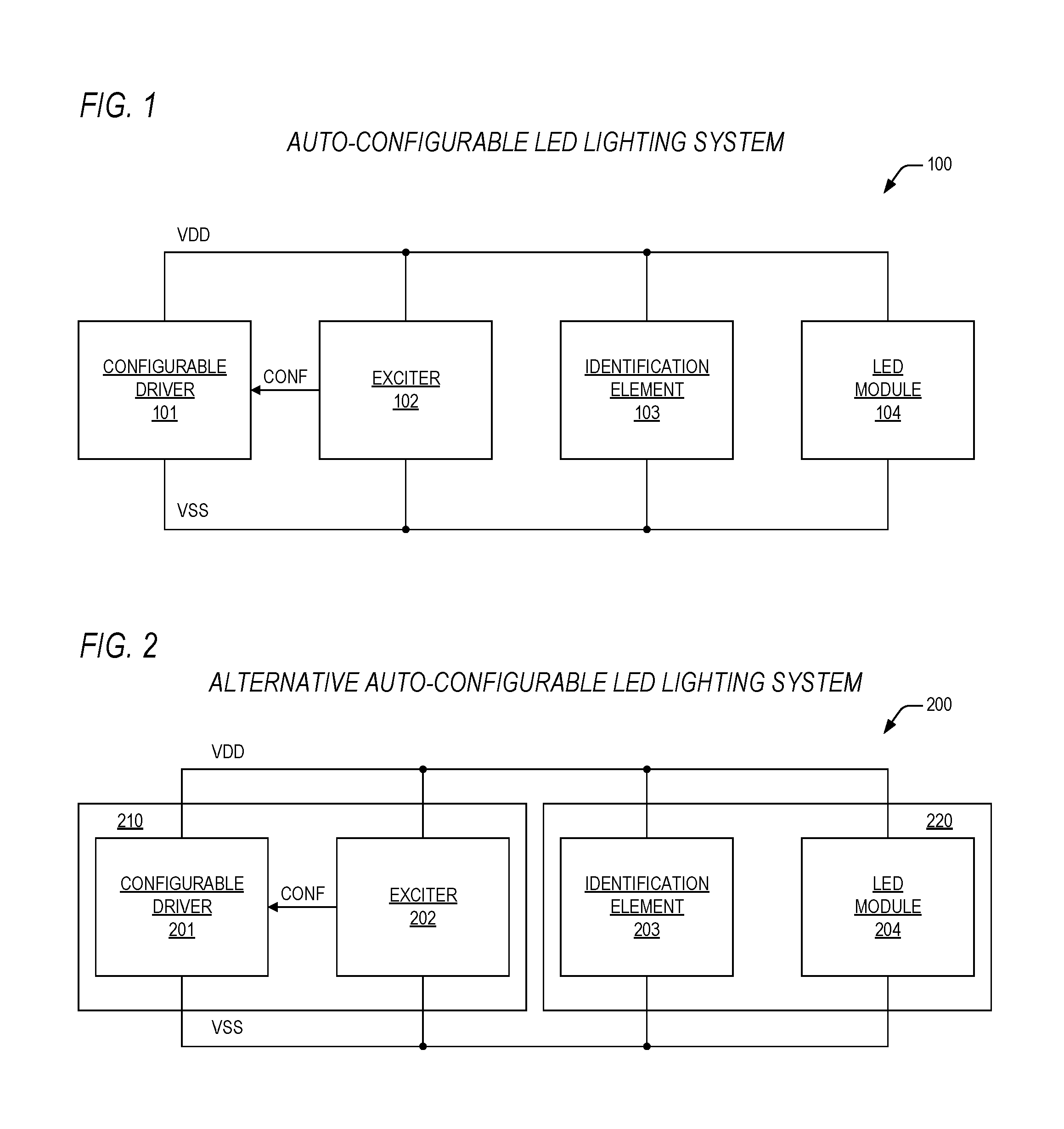
[0040]Turning now to FIG. 2, a block diagram is presented illustrating an auto-configurable LED lighting system 200 according to the present invention, where like named elements 201-204 function substantially in the same manner as those elements 101-104 of the LED lighting system of FIG. 1, the difference being that both the driver 201 and exciter 202 are physically disposed within a driver / exciter module 210, and the identification element 203 and LED module 204 are physically disposed within an auto-discoverable LED module 220. The driver / exciter module 210 according to the present invention is enabled to perform auto configuration and to drive any of a plurality of auto-discoverable LED modules 220 within a given class, as noted above. Advantageously, the system 200 of FIG. 2 provides for a single driver / exciter module 210 for the class such that any of the plurality of auto-discoverable LED modules 220 within the class may be driven, thus drastically lowering costs associated wi...

third embodiment

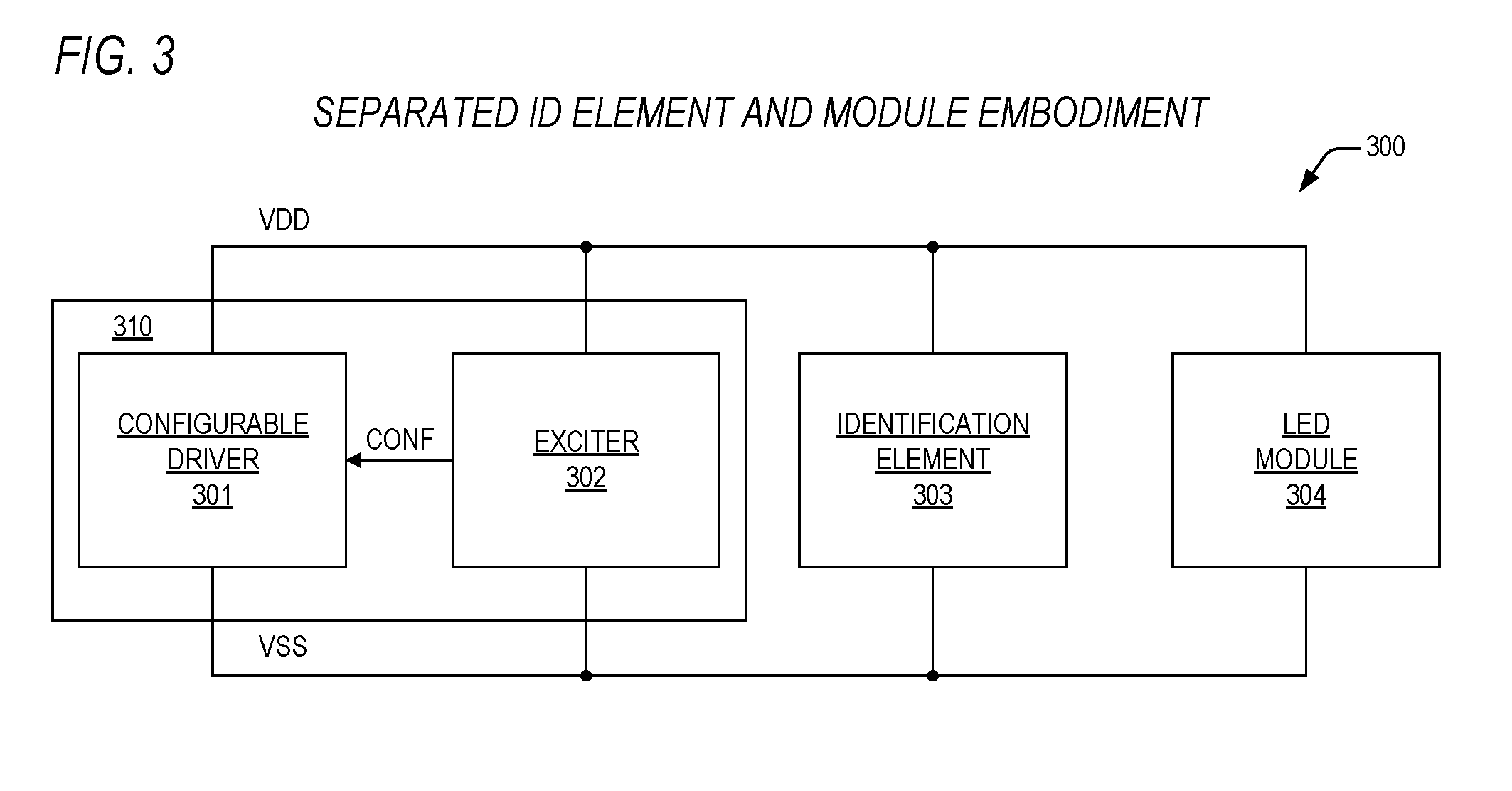
[0041]Referring now to FIG. 3, a block diagram is presented illustrating an auto-configurable LED lighting system 300 according to the present invention, where like named elements 301-304 function substantially in the same manner as those elements 101-104 of the auto-configurable LED lighting system 100 of FIG. 1, the difference being that in the embodiment of FIG. 3, both the configurable driver 301 and exciter 302 are physically disposed within a driver / exciter module 310, and the identification element 303 and LED module 304 are physically separate elements from the driver / exciter module 310 and from each other. Advantageously, the system 300 of FIG. 3 provides for a single driver / exciter module 310 for the class such that any of a plurality of LED modules 304 within the class may be driven by selecting corresponding identification elements 303, thus drastically lowering costs associated with installation. And while stocking costs may be incrementally more than those of the syste...


PUM


Abstract

An apparatus for automatically characterizing and configuring a light-emitting diode (LED) lighting system is provided. The apparatus includes a driver, an identification element, and an exciter. The driver is configured to provide a plurality of constant currents within a first range, a plurality of first voltages within a second range, at a plurality of maximum power levels within a third range over a power signal and a return signal, where the driver is configurable to drive the power and return signals to provide one of the plurality of constant currents, one of the first plurality of first voltages, and one of the plurality of maximum power levels to comport with operating characteristics of an LED module. The identification element is coupled to the driver, and is configured to exhibit a unique frequency response to excitation by excitation signals generated exclusively over the power and return signals at second voltages less than a lower bound of the second range. The exciter is coupled to the identification element and the driver via the power and return signals, and is configured to generate the excitation signals, and is configured to determine the one of the plurality of constant currents, the one of the plurality of first voltages, and the one of the plurality of maximum power levels based upon the unique frequency response, and is configured to configure the driver to comport with the operating characteristics.

Description

CROSS-REFERENCE TO RELATED APPLICATIONS[0001]This application claims the benefit of the following U.S. Provisional Application, which is herein incorporated by reference for all intents and purposes.SER.FILINGNO.DATETITLE62 / 153,023Apr. 27, 2015APPARATUS AND METHOD(FBQ.1010)FOR AUTOMATICCHARACTERIZATION ANDCONFIGURATION OFAN LED LIGHTING SYSTEMBACKGROUND OF THE INVENTION[0002]1. Field of the Invention[0003]This invention relates in general to the field of lighting, and more particularly to an apparatus and method for automatic characterization and configuration of a light-emitting diode (LED) lighting system.[0004]2. Description of the Related Art[0005]LED lighting systems are becoming increasingly more prevalent in new building designs as well as in retrofits for existing fluorescent and incandescent systems because of their low power usage and long lifetimes. In any size building (i.e., small, medium, large), one can look up and see a grid of, say, 2-foot by 4-foot lighting panels ...

Claims


Application Information

Patent Timeline
IPC IPC(8): H05B33/08H05B44/00
CPCH05B33/0806H05B33/0842H05B45/30H05B45/395
Inventor REH, JEFFREY G.O'KELLEY, MATTHEW B.
Owner FABRIQ
Learn More