

Display device
a display device and display panel technology, applied in the field of folding display devices, can solve the problem of large load on the display at the folded portion, and achieve the effect of reducing the risk of wrinkling
- Summary
- Abstract
- Description
- Claims
- Application Information
AI Technical Summary
Benefits of technology
Problems solved by technology
Method used
Image

Examples
embodiment 1
[0068](Display Device)
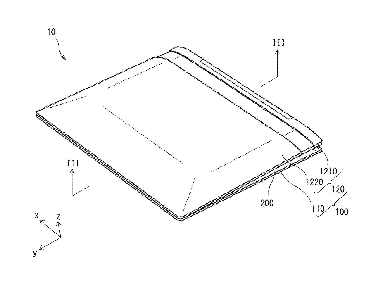
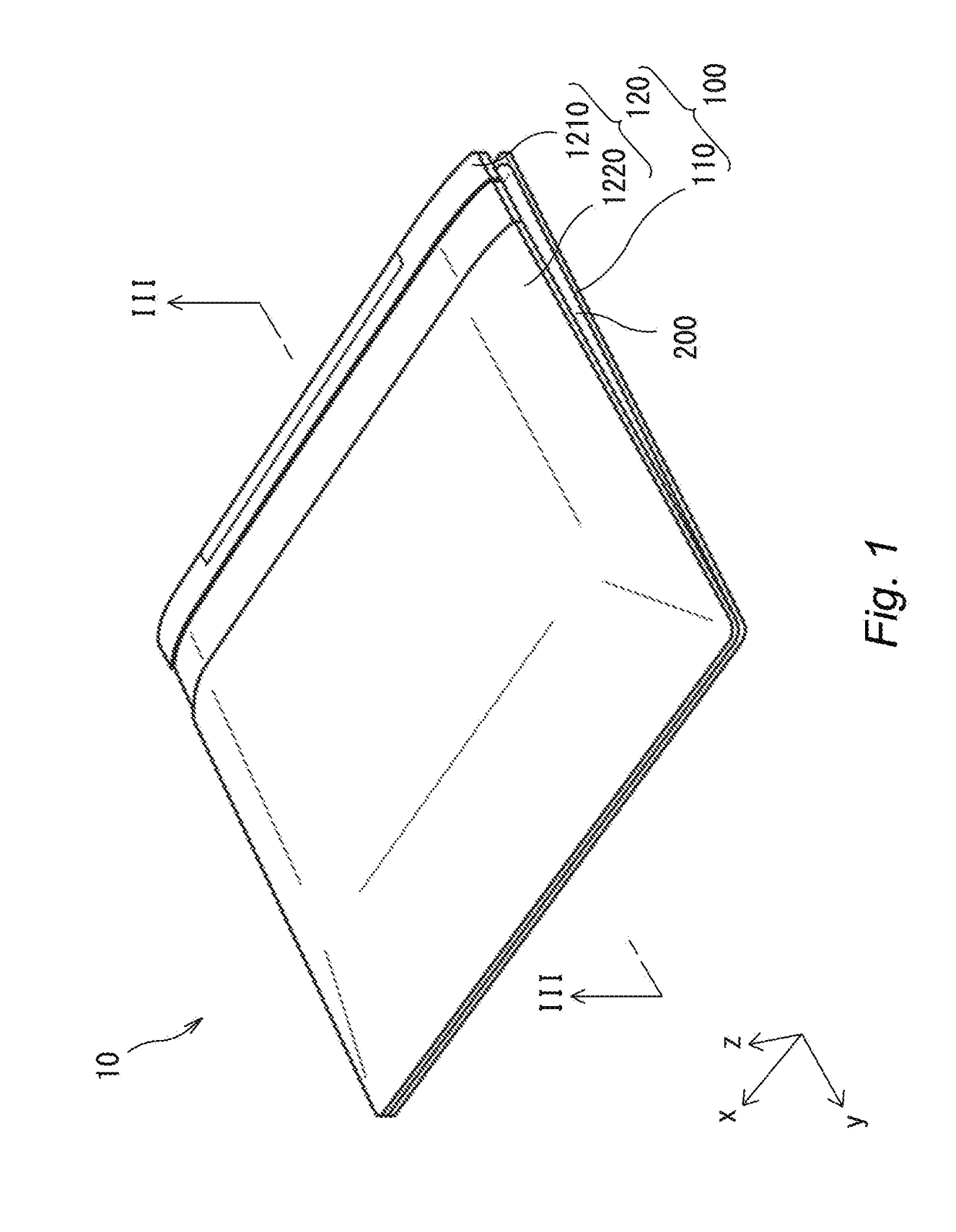
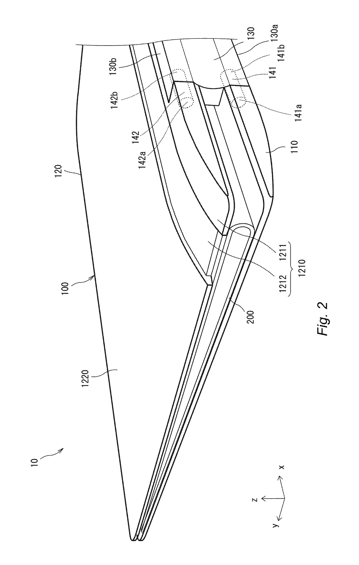
[0069]FIGS. 1 to 10 depicts a display device 10 according to the embodiment 1. The display device 10 includes a case unit 100 and a display panel 200. The case unit 100 is foldable to be deformed into a state where the case unit 100 is folded as in FIGS. 1 to 3, a state where the case unit 100 is opened as in FIGS. 4 to 6, and a state where the case unit 100 is fully opened as in FIGS. 7 to 10. FIGS. 1, 2, 4, 5, and 7 are perspective views of the display device 10. FIG. 3 is a sectional view taken along line indicated in FIG. 1. FIG. 6 is a sectional view taken along line VI-VI indicated in FIG. 4. FIGS. 8 and 9 are plan views of the display device 10. FIG. 10 is a sectional view taken along line X-X indicated in FIG. 7. The display device 10 depicted in FIG. 1 has dimensions about the A4 size or the like in the state where the case unit 100 is fully opened as in FIGS. 7 to 10.
[0070](Case Unit)
[0071]The case unit 100 includes a lower case 110 (first support mem...
modification examples
[0125]The present embodiment exemplifies the case where the flexible organic EL display panel is adopted as the display panel 200. The present invention is, however, not particularly limited to this case. Examples of the display panel 200 include a liquid crystal display panel provided with a film substrate, and electronic paper. The electronic paper can be of an electrophoretic type, a quick-response liquid powder type, a microcapsule type, or the like.
[0126]In a case where the display panel 200 is configured by the organic EL display panel, the electronic paper, or the like, which is easily bendable, the folded display panel 200 has a small curvature. In another case where the display panel 200 is configured by a flexible liquid crystal display panel or the like, which is not easily bendable, the folded display panel 200 needs to secure a large curvature and the adopted connecting plate 130 thus has a large width (dimension in the y direction in the fully opened display panel 200)...
embodiment 2
[0136]FIGS. 27 and 28 depict a display device 10C according to the embodiment 2. The display device 10C includes a case unit 100C and the display panel 200. The case unit 100C includes a lower case 110C, an upper case 120C, and the connecting plate 130. The upper case 120C includes the first member 1210 and a second member 1220C.
[0137]The lower case 110C includes a rib 115C provided at a surface opposite to a surface provided with the display panel 200. The rib 115C has a U shape following a peripheral edge portion of the lower case 110C. The rib 115C is 1 to 3 mm wide, for example. The rib 115C is 1 to 3 mm high, for example. The second member 1220C includes a rib 1225C provided at a surface opposite to a surface provided with the display panel 200. The rib 1225C has a U shape following the peripheral edge portion of the lower case 110C. The rib 1225C is 1 to 3 mm wide, for example. The rib 1225C is 1 to 3 mm high, for example. The display device 10C according to the embodiment 2 i...
PUM
 Abstract
Description
Claims
Application Information