
Robotic agricultural system and method

Active Publication Date: 2017-11-16
GUSS AUTOMATION LLC
View PDF2 Cites 20 Cited by
  • Summary
  • Abstract
  • Description
  • Claims
  • Application Information

AI Technical Summary

Benefits of technology

The patent describes a robotic agricultural system with autonomous delivery vehicles that can perform various agricultural tasks without overlapping paths or areas. The system includes a control center that communicates with the autonomous delivery vehicles to provide operational commands. The vehicles have sensors and a map to navigate the non-overlapping paths and areas. The system also includes a mobile control center and a mapper vehicle to generate the non-overlapping paths and areas. The autonomous delivery vehicles have hydraulic motors and a hydraulic system to drive them. The system can also include a collision avoidance system and a collision mitigation system to prevent collisions between the vehicles. The system can also have a command and control network and a video network to facilitate communication between the control center and the vehicles. The technical effects of the system include improved efficiency, precision, and safety in agricultural production.

Problems solved by technology

Modern agricultural equipment can be hazardous and labor-intensive to operate.
For example, current orchard spraying devices have exposed appendages and exposed moving parts that produce an aerosol of chemicals dangerous for human consumption.
Additionally, current orchard spraying devices can be clumsy and difficult to operate in an environment of a dense tree canopy, where the boughs of the trees hang low and the space between trees is thereby limited.
Typical equipment contacts the low-hanging tree boughs and may cause injury to the trees.
Moreover, operation of modern agricultural equipment can be a slow and tedious affair.
As a result, equipment operation progresses in fits and starts, continually limited by exhaustion and injury, governmental restrictions, and basic human needs.

Method used


Image

  • Robotic agricultural system and method
  • Robotic agricultural system and method
  • Robotic agricultural system and method

Examples


Embodiment Construction

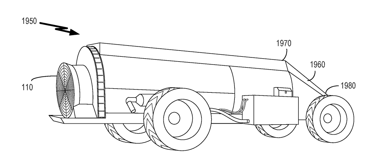
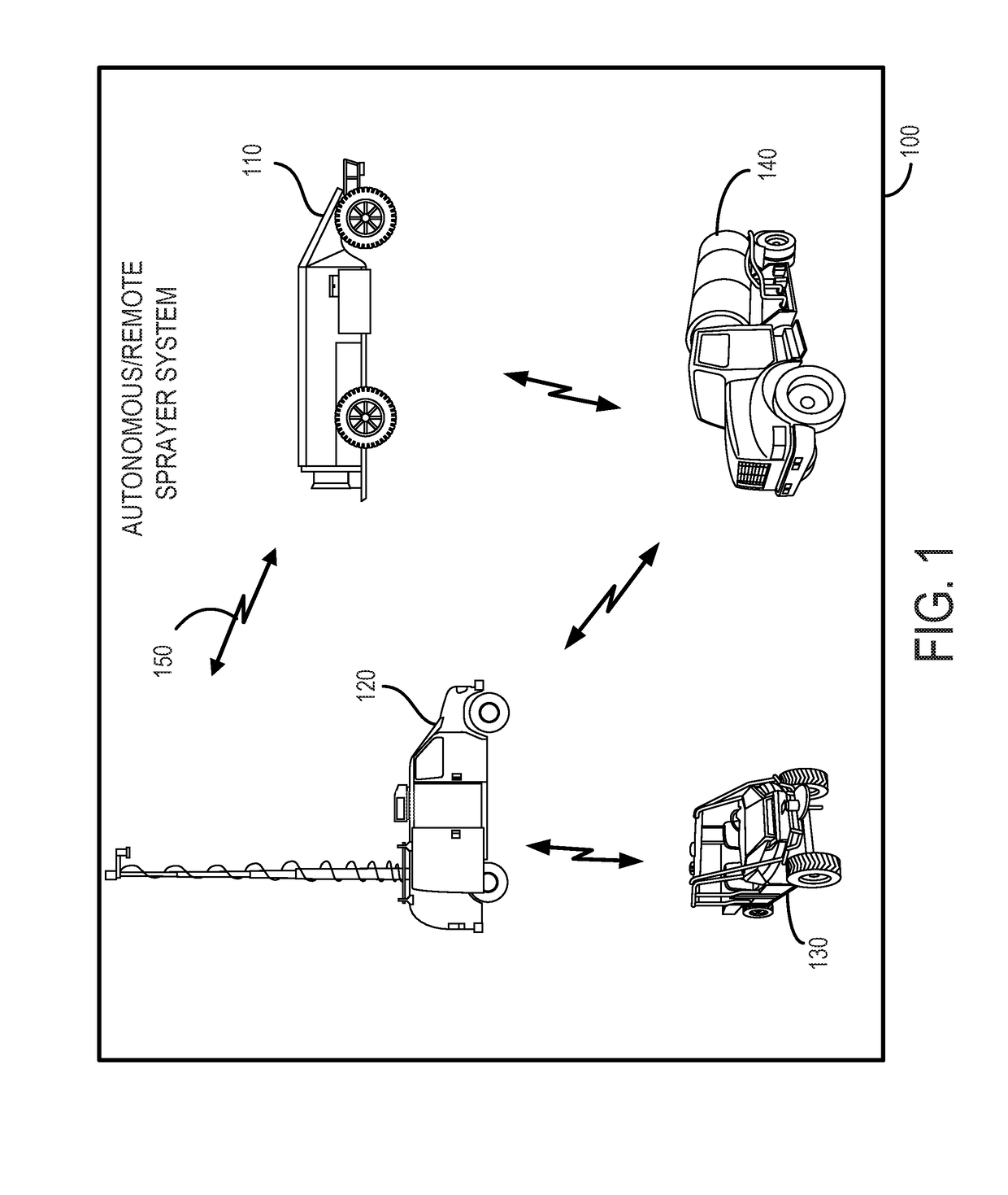
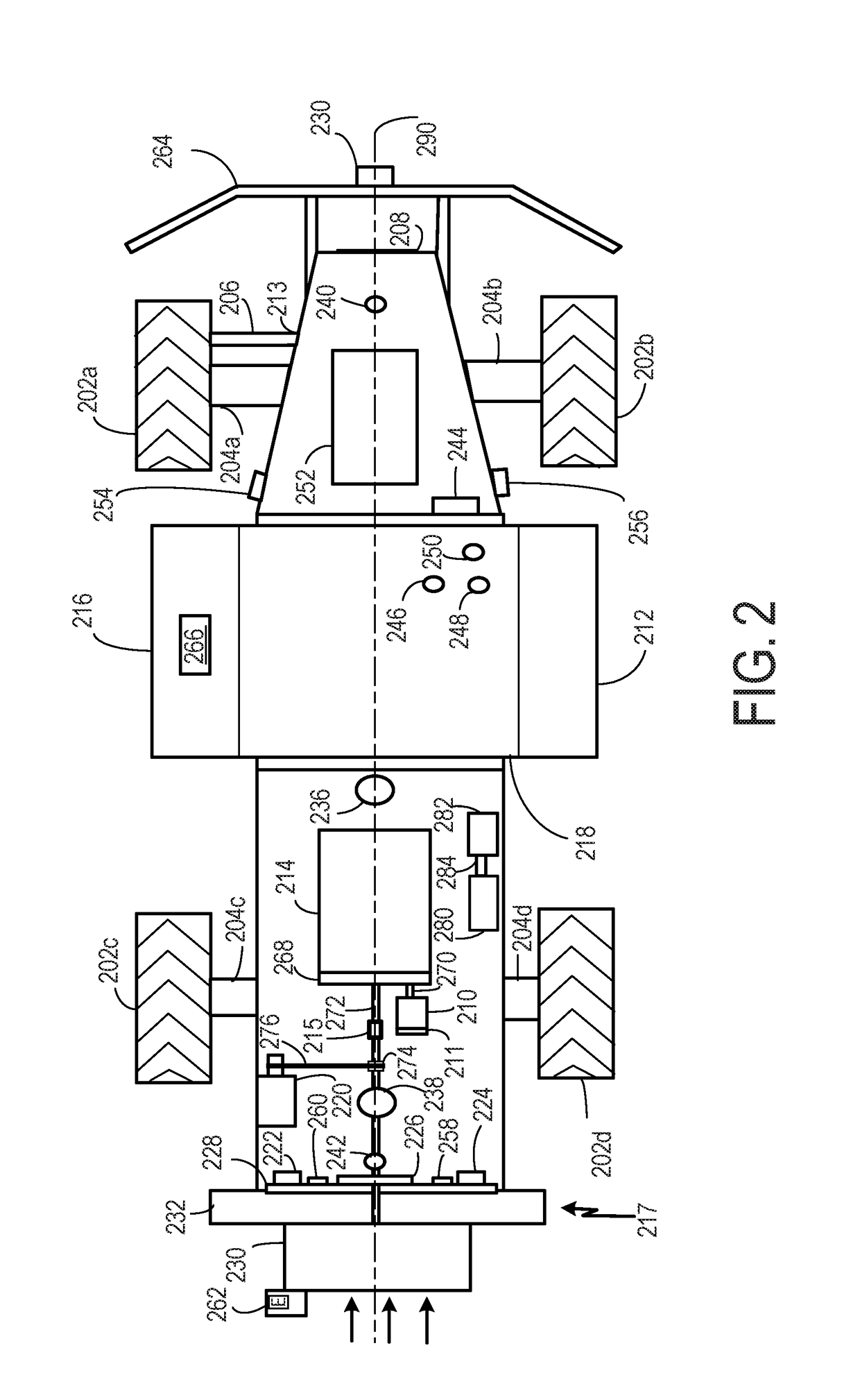
[0036]Embodiments herein are described within the non-limiting context of a tree orchard, although other embodiments including, without limitation, a viticulture context or a crop context, are possible, mutatis mutandi. Crops can be perennial or annual, or both. In addition, although agricultural spraying is explained in detail, all other agricultural purposes are possible, particularly those implementations suitable for mechanical or hydraulic actuation, including fertilizing, disking, plowing, tilling, or spreading. In general, an autonomous robotic sprayer is a type of autonomous delivery vehicle that is configured to autonomously perform a respective predetermined agricultural task. A fleet of autonomous delivery vehicles can be used to perform one or more respective predetermined agricultural tasks at a time in an orchard, a vineyard, or a field of crops, including perennial crops.

[0037]Continuing with the spraying example, an autonomous delivery vehicle—sprayer can allow a sin...


PUM


Abstract

A robotic orchard spraying system having autonomous delivery vehicles (ADV), each autonomously delivering an amount of a premixed solution over a non-overlapping path verified by a forward-looking sensor, video, or both. Also, a mobile control center, configured to wirelessly inform the autonomous delivery vehicle of the path within the areas and to confirm that the autonomous delivery vehicle is following the path within the area. Additionally, a mapper vehicle generates the path within the area, the mapper vehicle being configured to communicate information about the path and the area to the command center. The mapper vehicle senses the path with a forward-looking LiDAR sensor, and senses the area with a GPS sensor. Moreover, a nurse truck has a reservoir of premixed solution for replenishing a tank of the ADV. ADVs and the control center communicate over a radio network, which may be a mesh network, a cellular network, or both.

Description

BACKGROUND1. Field of the Invention[0001]The present invention pertains to agricultural equipment, in general, and robotic agricultural spraying equipment, in particular.2. Background Technology[0002]Modern agricultural equipment can be hazardous and labor-intensive to operate. For example, current orchard spraying devices have exposed appendages and exposed moving parts that produce an aerosol of chemicals dangerous for human consumption. This is particularly the case when pesticides and fungicides are being sprayed on the orchard trees. Equipment operators are required to wear confining respirators and goggle to avoid incidental contact with the sprayed agent. Additionally, current orchard spraying devices can be clumsy and difficult to operate in an environment of a dense tree canopy, where the boughs of the trees hang low and the space between trees is thereby limited. Typical equipment contacts the low-hanging tree boughs and may cause injury to the trees. Also, the operator mu...

Claims


Application Information

Patent Timeline
IPC IPC(8): A01M7/00G05D1/02G05D1/00B05B12/12
CPCA01M7/0014G05D1/0022G05D1/0038G05D1/0246G05D1/0061G05D1/0094G05D1/0297G05D1/0289B05B12/122G05D1/024G05D1/0274G05D1/0278A01B69/008A01B79/00B05B7/32B05B13/005A01M7/0089
Inventor CRINKLAW, DAVID CURTISSCHAPANSKY, CHASEVACCARI, RICHARDBISCHEL, JEREMYJOHNSON, RYAN
Owner GUSS AUTOMATION LLC
Learn More