Implantable electrode configuration

a technology of implantable electrodes and configuration, which is applied in the field of implantable electrode configuration, can solve the problems of ineffective action, inability to penetrate into extremely small cracks and interspaces, and inability to increase the mechanical fastening of metal-polymer hybrids in the area,

Active Publication Date: 2017-11-16
NEUROLOOP
View PDF1 Cites 2 Cited by
  • Summary
  • Abstract
  • Description
  • Claims
  • Application Information

AI Technical Summary

Benefits of technology

[0007]The invention is an improvement of an implantable electrode configuration having a carrier substrate made of a biocompatible polymer or polyimide in at least some areas, a freely accessible electrode surface of an electrode applied to the carrier substrate or integrated int

Problems solved by technology

Thus, intracorporeal liquids, for example, have a tendency to penetrate into extremely small cracks and interspaces on technical-grade surfaces in particular due to their capillary spreading and wetting properties, so that electrode structures, which are applied mainly to carrier substrate surfaces and enclose an interface that is constantly exposed to the capillary fluid, are constantly exposed to a fluid-mechanical releasing effect because of the difference in material between the carrier substrate of at

Method used


Image

  • Implantable electrode configuration
  • Implantable electrode configuration
  • Implantable electrode configuration

Examples


Embodiment Construction

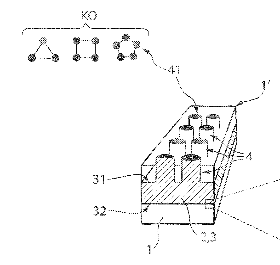
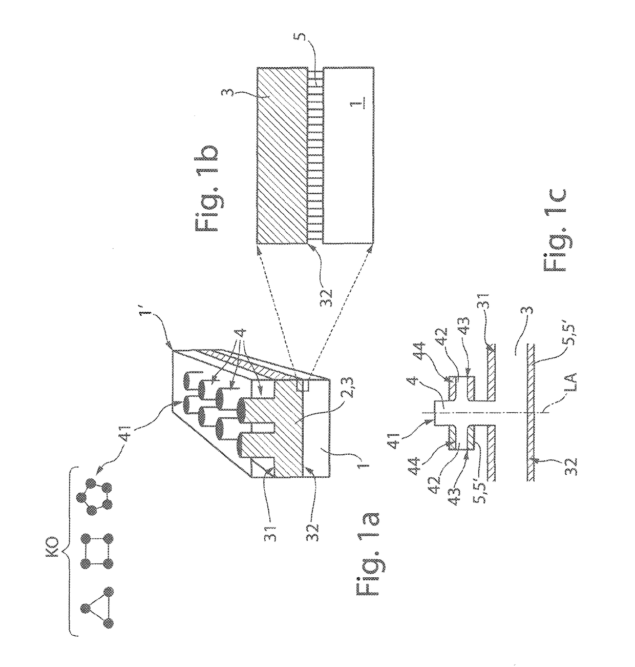
[0019]To permanently improve the joining of an electrode body 2, for example, in the form of an electrode strip in or on a carrier substrate 1 made of a biocompatible polymer material, it is proposed that the electrode strip 3 be integrated extensively into the carrier substrate 1 in the following manner as shown in FIG. 1a.

[0020]The electrode body 2 has a metallic base plate 3, which has a top side 31 and a bottom side 32. Orthogonally elevated structural elements 4 are connected in one piece to the top side 31 of the base plate 3 and are preferably distributed over the entire area of the top side. These structural elements preferably are in the form of protrusions shaped like columns, ribs, webs or sleeves, over a surface area 41 facing the carrier substrate surface 1′ as shown in FIG. 1a, which can come into direct contact with the epineurium, for example, of a nerve fiber bundle in the implanted state of the electrode configuration. In addition, an adhesion promotion layer 5 is...


PUM


Abstract

The invention is an implantable electrode configuration having a carrier substrate of a biocompatible polymer in at least some areas and a freely accessible electrode surface applied to the carrier substrate or integrated into the carrier substrate on the carrier substrate surface in at least some areas is described and a method for producing the implantable electrode configuration. The electrode has a metallic base plate having a planar top side and bottom side, including at least one structural element protruding orthogonally from the top side. The planar surface of the metallic base plate is oriented parallel to the carrier substrate surface and the metallic base plate is enclosed by the biocompatible polymer, except for a first surface area of the at least one structural element which faces the carrier substrate surface and is the freely accessible electrode surface.

Description

CROSS-REFERENCE TO RELATED APPLICATIONS[0001]Reference is made to International Application No. PCT / EP2015 / 073132 filed Oct. 7, 2015, and German Patent Application No. 102014014943.9, filed Oct. 7, 2014, which applications are incorporated herein by reference in their entirety.BACKGROUND OF THE INVENTIONField of the Invention[0002]The invention relates to an implantable electrode configuration with a carrier substrate of biocompatible polymer or polyimide in at least some areas, and a freely accessible electrode surface of an electrode applied to the carrier substrate or integrated into the carrier substrate present on the carrier substrate surface in at least some areas.Description of the Prior Art[0003]Medical implants used for the purposes of supplying and / or diverting electric signals into and / or out of regions located intracorporeally usually have metallic line structures with freely accessible electrode surfaces, which come into direct contact with the intracorporeal tissue ar...

Claims


Application Information

Patent Timeline
IPC IPC(8): A61N1/36A61N1/32A61N1/05A61N1/372
CPCA61N1/3605A61N1/059A61N1/326A61N1/057A61N1/37247A61N1/05
Inventor PLACHTA, DENNISGIEHRTMUEHLEN, MORTIMERSTIEGLITZ, THOMASZENTNER, JOSEF
Owner NEUROLOOP
Why Eureka
Try Eureka