Large water hole bypass valve for screw drill

A water hole bypass, screw drilling tool technology, applied in earth-moving drilling, flushing wellbore, wellbore/well components, etc. Improved, simple structure, reduced loss effect

Inactive Publication Date: 2015-03-04
TIANJIN LILIN GASOLINEEUM MACHINERY
View PDF1 Cites 3 Cited by
  • Summary
  • Abstract
  • Description
  • Claims
  • Application Information

AI Technical Summary

Problems solved by technology

[0002] At present, when downhole screw drilling tools are used in oil and gas drilling engineering, in order to balance the pressure inside and outside the drilling tool during the tripping process, the drilling mud in the drilling tool can quickly flow into the wellbore during the tripping process without Take it to the ground to pollute the drill floor, and make the drilling fluid become the mechanical power to push the drill bit during the drilling process. Generally, there is a drilling tool bypass valve in the drilling tool combination, such as the anti-puncture bypass valve that the applicant has applied for recently. , Publication No.: CN 104033117 A, the spool, spring and valve seat of the general drilling tool bypass valve are sequentially loaded into the valve body from the male joint end of the valve body, and a retaining ring groove is arranged on the inner edge of the valve body. Install the retaining ring to prevent the valve core and valve seat from falling into the well. Since the inner hole of the valve core is much smaller than the inner hole of the drill string during the entire drilling process, an unnecessary pressure rise and flow speed will be generated during the drilling process. , causing a certain impact and pressure loss on the screw drilling tool

Method used


Image

  • Large water hole bypass valve for screw drill
  • Large water hole bypass valve for screw drill

Examples


Embodiment Construction

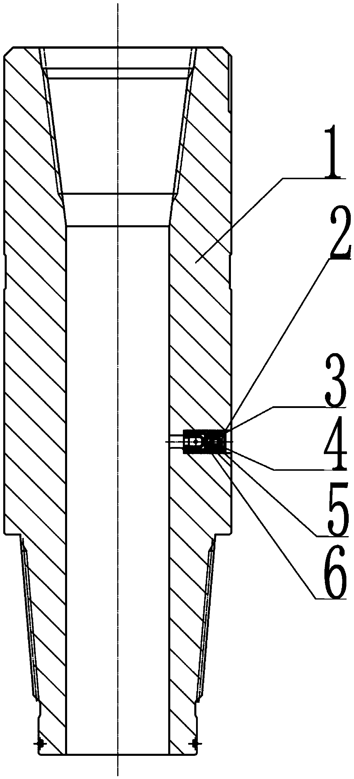
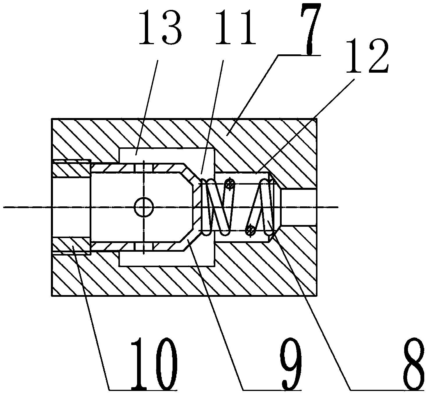
[0011] The specific implementation manner of the present invention will be described in detail below in conjunction with accompanying drawing and preferred embodiment, as figure 1 As shown, a large water eye bypass valve for screw drilling tools includes a bypass valve body 1, and a circlip 2, a partition 3, and a screen installed in the bypass hole of the bypass valve body in sequence. plate 4, partition 5, and a one-way valve 6 is also installed in the bypass hole, such as figure 2 As shown, the one-way valve 6 is mainly composed of a one-way valve body 7, a spring 8, a valve core 9 and an inner hexagonal nut 10. The one-way valve body is provided with a stepped inner hole 11, and the spring is placed In the small hole 12 in the stepped inner hole of the one-way valve body, one end of the spring is connected to the top end of the valve core, and the valve core is placed in the large hole in the stepped inner hole of the one-way valve body. In the hole 13, the end of the va...


PUM


Abstract

The invention relates to the technical field of manufacturing of petroleum drilling tools, in particular to a large water hole bypass valve for a screw drill. The large water hole bypass valve comprises a bypass valve body, and a snap spring, a spacing plate, a sieve plate and a spacing plate mounted in a bypass hole of the bypass valve body in sequence, wherein a one-way valve is additionally mounted in the bypass hole, and mainly consists of a one-way valve body, a spring, a valve core and an internal hexagonal nut; a step-shaped inner hole is formed in the one-way valve body; the spring is positioned in a small hole of the step-shaped inner hole of the one-way valve body; one end of the spring is connected with the top end of the valve core; and the hexagonal nut is in threaded connection with the one-way valve body. Such parts as valve cores and valve sleeves with conventional model numbers in the bypass valve body are reduced, so that the internal structure is simple, is easy to be processed, and is convenient to be assembled; and the parts can be conveniently replaced in a well mouth, so that the maintenance cost is saved. The internal annulus of the bypass valve body is largely improved, so that the vertical pipe pressure loss is reduced.

Description

technical field [0001] The invention relates to the technical field of petroleum drilling tools, in particular to a large water hole bypass valve for a screw drilling tool. Background technique [0002] At present, when downhole screw drilling tools are used in oil and gas drilling engineering, in order to balance the pressure inside and outside the drilling tool during the tripping process, the drilling mud in the drilling tool can quickly flow into the wellbore during the tripping process without Take it to the ground to pollute the drill floor, and make the drilling fluid become the mechanical power to push the drill bit during the drilling process. Generally, there is a drilling tool bypass valve in the drilling tool combination, such as the anti-puncture bypass valve that the applicant has applied for recently. , publication number: CN 104033117 A, the spool, spring and valve seat of the general drilling tool bypass valve are sequentially loaded into the valve body from...

Claims


Application Information

Patent Timeline
Patent Type & Authority Applications(China)
IPC IPC(8): E21B21/10
CPCE21B21/10
Inventor 赵春雨黄玉明罗绪良
Owner TIANJIN LILIN GASOLINEEUM MACHINERY
Why Eureka
Try Eureka