
Apparatus and method for cutting or embossing coatings

Inactive Publication Date: 2017-11-16
NESTEC SA
View PDF0 Cites 32 Cited by
  • Summary
  • Abstract
  • Description
  • Claims
  • Application Information

AI Technical Summary

Benefits of technology

The invention has two main benefits. Firstly, it creates a very precise cutting pattern. Secondly, it reduces the force needed to push or pull the product through the cutting mechanism. This makes it easier for accidentally stuck products to be released.

Problems solved by technology

However, due to the very close characteristic, both jelly shell and core, or the different layers of jelly, can be found to adhere to each other and may be difficult to peel apart from each other during consumption in particular for children who enjoy these kinds of composite frozen confectionery products.
The industrial application of such cut lines, however, constitutes a technical challenge.
While other shapes of cut lines than a spiral can principally be manufactured using that process, it has been found this procedure has limitations when applied to vertical cut lines for generally cylinder-shaped products.
In particular, the process meets limitations if more than two cut lines, such as 3, 4 or more lines, are to be produced with the lines evenly distributed around the circumference of the product.
The problems arise from the fact that on modern production lines, the products are arranged in rows of typically 4 to 20 or more products side-by-side.
Even if the gap is large enough to accommodate such mechanisms, such a procedure would require a complex mechanical installation.
One problem with the current cutting mechanisms is that it provides mechanical stress on the production line when products are moved up and down.
Furthermore, for frozen confection products in the form of a stick with longitudinal cut lines, it was found that the products tend to remain stuck in the cutter or they that may break apart during the process of cutting of the coating.

Method used


Image

  • Apparatus and method for cutting or embossing coatings
  • Apparatus and method for cutting or embossing coatings
  • Apparatus and method for cutting or embossing coatings

Examples


example 1

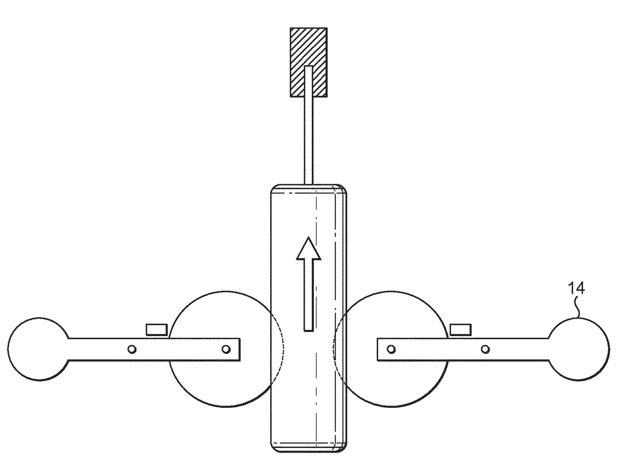
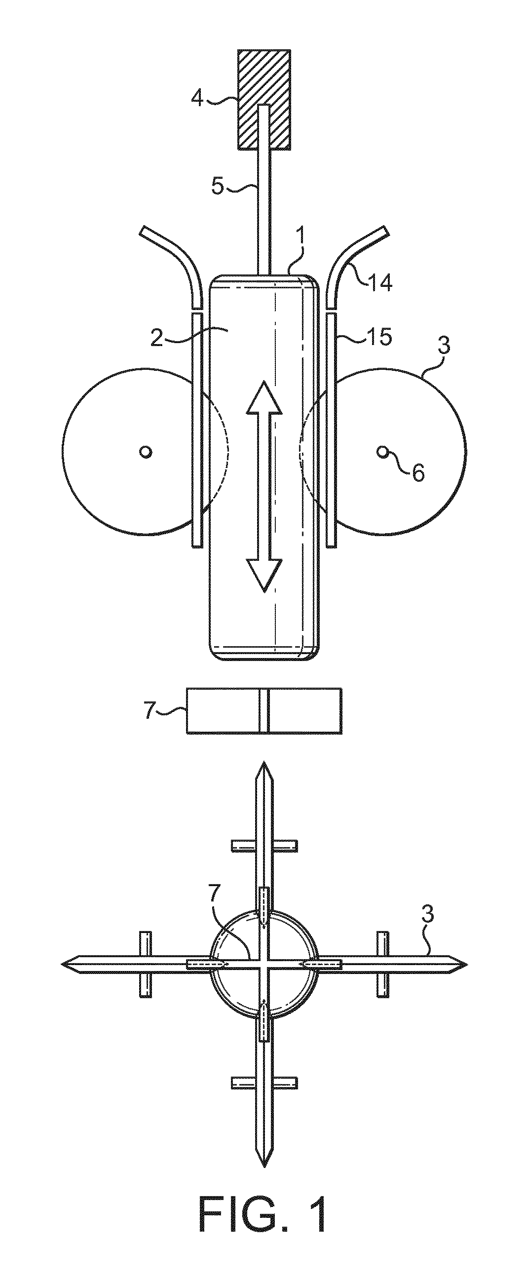
[0085]FIG. 1 schematically depicts a coating cutting tool with a set of 2 disk-shaped side knives (3) oriented around the product void (2) into which the product (1) is introduced and subsequently retracted by means of a gripper (4) holding the product by it's stick (5). The number of knives can be two or more. Typically, the number of knifes is 4. The knives consist of sharp disk blades which are mounted on an axis (6) in a way that allows them to rotate as the product is inserted and retracted, while reaching through the skin layer of the product up to the core layer. The product is pushed into the product void until the desired length of the cut is achieved. The figures shows a side view of product (1) hold on the stick (5) by a gripper (4). The end knife (7) is located beneath the product. Also shown is a schematic top view showing 4 side knives (3) and the cross shaped end knife (7) with both sets of knifes being in alignment to generate a cutting groove that is continuous betw...

example 2

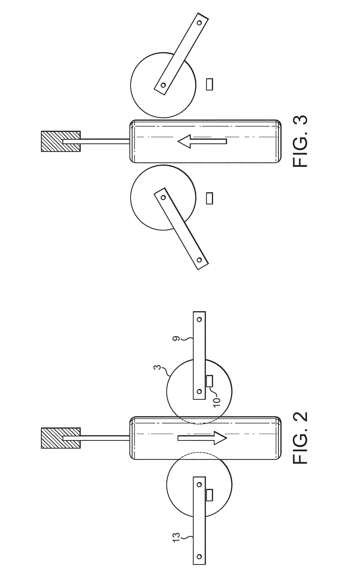
[0086]The embodiment of the invention shown in FIG. 2 uses disk-shaped side knives (3), which are fixed on a rotatable mechanism (13). Said rotatable mechanism allows rotation around axis (9) up to a limitation imposed by blocking means (10). A product being introduced into the product void is thus cut during the down movement as the knives are in a cutting position. When the product is retracted back (FIG. 3), the rotatable mechanism allows the disk-shaped side knifes to swing upwards and out of the way in order not to impose any resistance towards the up-movement of the product. This is of advantage in case of products accidentally getting stuck inside the knife assembly. Such products have to be manually pushed out, e.g. by means of a stick or a hook. Doing so against the resistance of the disk knifes is hard. With the knives swinging out of the way, this action is greatly facilitated, making handling of such irregularities easier

example 3

[0087]The embodiment of the invention shown in FIG. 4 relates to the movement of the coating cutting tool along the product axis while applying the cuts. In this example, the product is not lowered into the coating cutting. Instead, the coating cutting tool is raised to become inserted into the static product. After application of the cut, the coating cutting tool is retracted back down. The advantage of this set-up consists in eliminating the need to forcefully lower and raise the product, thereby avoiding any mechanical stress on the production line


PUM


Abstract

The invention relates to a coating cutting tool for frozen confection comprising a frame defining a product void for receiving a product at least partly coated, a set of disk-shaped side knives comprising at least two knives mounted on the frame opposite of the product void, wherein the knives are rotatable arranged on the frame such that they can be rotated into a product coating cutting position for cutting the coating on the side of the product and out of such a position to a non-engaging position to allow the product to be moved passed the knives, and an end knife for cutting the coating on the end of the frozen confection. The invention also relates to a method for cutting a coating on a frozen confection.

Description

FIELD OF THE INVENTION[0001]The present invention relates to an apparatus and a method for making a frozen confectionery product with a peelable confectionery coating. In particular the invention relates to an apparatus and method for automatically applying cutting or embossing lines to a confectionery coating, especially a gel coating, during the production on an industrial manufacturing line.BACKGROUND[0002]Frozen confectionery products consisting entirely of frozen gel or comprising a frozen gel coating are known and are popular in particular with children.[0003]One example is a frozen confectionery product comprising a core consisting of a frozen confection said core being at least partially coated with a frozen flexible edible gel coating or layer. Such a frozen confectionery product is sold by Nestlé Thailand under the brand name “Eskimo Monkey”. This product comprises an ice-cream core being coated with a frozen flexible edible gel layer. This gel layer can be peeled off by t...

Claims


Application Information

Patent Timeline
IPC IPC(8): B26D3/08A23G9/28A23G9/22A23G9/26A23G9/50A23G9/48
CPCB26D3/08A23G9/22A23G9/26A23G9/285A23G9/48A23G9/503B26D3/001
Inventor AMEND, THOMAS ALOISIUS VALENTINUS
Owner NESTEC SA
Learn More