Vehicle air-conditioning device

a technology for air conditioning devices and vehicles, applied in vehicle heating/cooling devices, vehicle components, transportation and packaging, etc., can solve problems such as and achieve the effect of suppressing deterioration of energy efficiency

Active Publication Date: 2017-11-16
HIGHLY MARELLI JAPAN CORPORATION
View PDF11 Cites 21 Cited by
  • Summary
  • Abstract
  • Description
  • Claims
  • Application Information

AI Technical Summary

Benefits of technology

[0006]In this aspect, by a refrigeration cycle, the heat is transferred via cooling medium from a first coolant-water circulation path in which coolant water passes through an engine to a second coolant-water circulation path in which the coolant water passes through a vehicle-cabin radiator. In addition, the communication through the first coolant-water circulation path and the second coolant-water circulation path can be shut off by a shutting off mechanism. Therefore, when the shutting off mechanism is switched to a shut-off state, the coolant water circulating in the second coolant-water circulation path is prevented from being reheated after cooled once. Thus, it is possible to suppress deterioration of the energy efficiency caused by reheating of the coolant water.

Problems solved by technology

Therefore, there is a risk in that energy efficiency may be deteriorated due to reheating of the engine coolant water that has been cooled once.

Method used


Image

  • Vehicle air-conditioning device
  • Vehicle air-conditioning device
  • Vehicle air-conditioning device

Examples


first embodiment

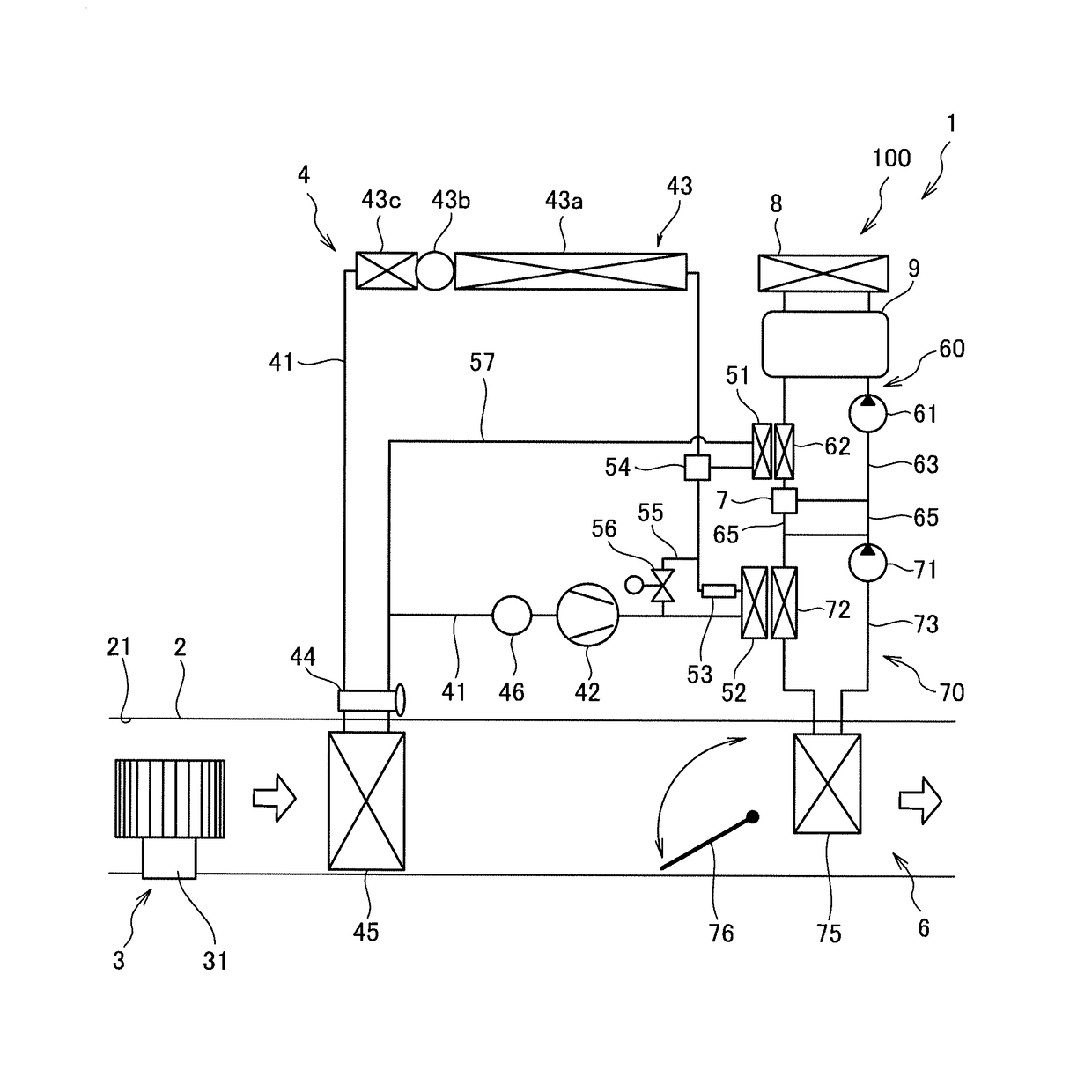
[0020]An overall configuration of a vehicle air-conditioning device 100 according to a first embodiment of the present invention will be described with reference to FIG. 1.

[0021]The vehicle air-conditioning device 100 is an air-conditioning device that is mounted on a vehicle 1, such as a hybrid vehicle (a Hybrid Electric Vehicle: HEV), having an engine-stopping function that stops an engine when the vehicle is stopped or driven. The vehicle 1 includes an engine 9 that is used for driving wheels and generating electricity and a radiator 8 that cools the engine 9 with the circulating coolant water.

[0022]The vehicle air-conditioning device 100 includes an air duct 2 having an air intake port 21, a blower unit 3 that introduces air from the air intake port 21 into the air duct 2, a heat pump unit 4 serving as a refrigeration cycle that cools and dehumidifies the air flowing through the air duct 2, and a heater unit 6 that warms the air flowing through the air duct 2.

[0023]The air that ...

second embodiment

[0101]Next, a vehicle air-conditioning device 200 according to a second embodiment of the present invention will be described with reference to FIG. 12. In the second embodiment, components that are similar to those in the first embodiment described above are assigned the same reference signs, and repetitive description thereof shall be omitted appropriately.

[0102]In the second embodiment, a belt driven compressor 47 is applied instead of the electric compressor 42. In addition, a sub-heat pump unit 5 serving as a sub-refrigeration cycle that transfers the heat of the coolant water in the coolant-water circulation path 63 to the coolant water in the coolant-water circulation path 73 is provided separately from the heat pump unit 4.

[0103]In the second embodiment, as in the first embodiment, the operation can be performed in the heat pump heating-operation mode, the engine heating-operation mode, the cooling-operation mode, and the coldness-storing mode. In the second embodiment, the ...


PUM


Abstract

A vehicle air-conditioning device includes: a first coolant-water circulation path in which coolant water passes through an engine ; a second coolant-water circulation path that is communicated with the first coolant-water circulation path and in which the coolant water passes through a vehicle-cabin radiator; a shutting off mechanism that shuts off, when switched to a shut-off state, the communication between the first coolant-water circulation path and the second coolant-water circulation path; and a refrigeration cycle. The refrigeration cycle has: a compressor for compressing cooling medium; a secondary evaporator in which the cooling medium absorbs heat from the coolant water in the first coolant-water circulation path; a secondary condenser that releases heat of the cooling medium that has absorbed the heat at the secondary evaporator to the coolant water in the second coolant-water circulation path; and a secondary expander that decompresses the cooling medium that has passed through the secondary condenser.

Description

TECHNICAL FIELD[0001]The present invention relates to a vehicle air-conditioning device.BACKGROUND ART[0002]JP2011-131871A discloses a vehicle air-conditioning device that is mounted on a hybrid vehicle and that circulates engine coolant water between a heater core and an engine to heat air that has passed through an evaporator by performing heat exchange between the engine coolant water and the air. This vehicle air-conditioning device includes a heat-absorbing side heat exchanger that is provided at the downstream side of the heater core, a heat-releasing side heat exchanger that is provided at the upstream side of the heater core, and a Peltier device that is provided between the heat-absorbing side heat exchanger and the heat-releasing side heat exchanger. With this device, when the engine is stopped, temperature of the engine coolant water that flows into the heater core is prevented from being decreased by transferring heat via the Peltier device from the engine coolant water ...

Claims


Application Information

Patent Timeline
Patent Type & Authority Applications(United States)
IPC IPC(8): B60H1/00B60H1/32
CPCB60H1/00807B60H1/00385B60H1/00885B60H1/3211B60H1/00921B60H1/3213B60H1/323B60H2001/00928B60H1/32281B60H1/32284
Inventor HATAKEYAMA, JUNOGIHARA, SATOSHIOHNO, HIROYUKI
Owner HIGHLY MARELLI JAPAN CORPORATION
Why Eureka
Try Eureka