Drinking water supply device and water dispenser

A technology for a supply device and a water dispenser, which is applied to beverage preparation devices, applications, kitchen utensils, etc., can solve problems such as inconvenience, energy consumption, and adverse human health, and achieve the effect of reducing power consumption.

Pending Publication Date: 2017-03-08
GUANGDONG POLYTECHNIC NORMAL UNIV
View PDF17 Cites 6 Cited by
  • Summary
  • Abstract
  • Description
  • Claims
  • Application Information

AI Technical Summary

Problems solved by technology

[0004] The first purpose of the present invention is to provide a drinking water supply device to solve the problem that the drinking water supply device in the prior art may process "thousand boiling water" and "yin and yang water", which is not conducive to human health, serious energy consumption and inconvenient use. technical problem

Method used


Image

  • Drinking water supply device and water dispenser
  • Drinking water supply device and water dispenser
  • Drinking water supply device and water dispenser

Examples


Embodiment 1

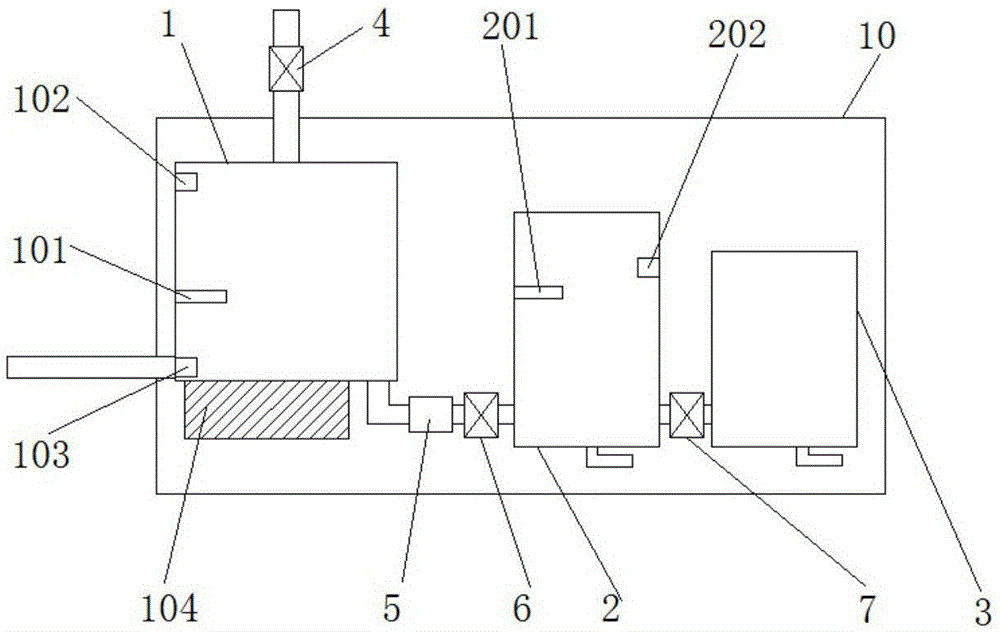
[0031] Present embodiment one is a kind of drinking water supply device, with reference to figure 1 As shown, it includes a control circuit, a heating tank 1, a warm water tank 2 and a cold water tank 3 connected in series in sequence. The heating tank 1 is provided with a water inlet pipe, and the heating tank 1, warm water tank 2 and cold water tank 3 are respectively provided with outlet pipes. The water inlet pipe is provided with a first solenoid valve 4, a flow meter 5 and a second solenoid valve 6 are arranged between the heating tank 1 and the warm water tank 2 in sequence, and a third solenoid valve 7 is arranged between the warm water tank 2 and the cold water tank 3 The heating box 1 is provided with a heating box temperature sensor 101, a liquid level sensor 102 on the heating box and a liquid level sensor 103 under the heating box, and the outside of the heating box 1 is provided with a heating device 104 for heating the heating box 1, and the warm water tank 2 Th...

Embodiment 2

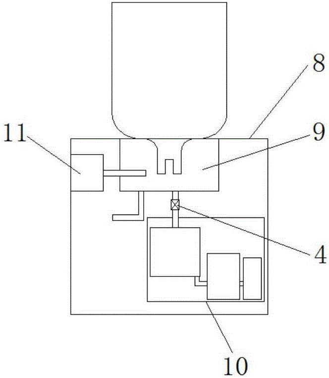
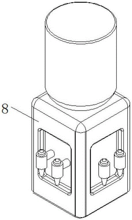
[0046] Present embodiment two is a kind of water dispenser, with reference to figure 2 As shown, it includes a chassis body 8, a switch disposed on the chassis body 8, and a drinking water supply device in Embodiment 1. The drinking water supply device is arranged inside the chassis body 8; the switch is electrically connected to the control circuit; the top of the chassis body 8 is provided with The water storage tank 9 communicates with the heating box 1 through the water inlet pipe.

[0047] Wherein, the free end of the water outlet pipe communicated with the heating tank 1 , the warm water tank 2 and the cold water tank 3 is placed outside the cabinet body 8 .

[0048] The water dispenser of this embodiment controls the opening and closing of the entire water dispenser through a switch arranged on the cabinet body 8 . Using this water dispenser, when the user turns on the switch once, no matter whether the demand for drinking water is large, the demand for drinking water...


PUM


Abstract

The invention provides a drinking water supply device and a water dispenser, and relates to the technical field of water dispensers. The drinking water supply device comprises a control circuit, and a heating tank, a hot water tank and a cold water tank which are sequentially connected serially and communicated, wherein a first electromagnetic valve is arranged on a water inlet pipe; a flow meter and a second electromagnetic valve are sequentially arranged between the heating tank and the hot water tank; a third electromagnetic valve is arranged between the hot water tank and the cold water tank; a heating tank temperature sensor, an upper heating tank liquid level sensor and a lower heating tank liquid level sensor are arranged inside the heating tank; a heating device for heating for the heating tank is arranged on the outer part of the heating tank; a hot water tank temperature sensor and a hot water tank liquid level sensor are arranged inside the hot water tank. The technical problems that the conventional drinking water supply device may produce repeatedly boiling water and mixed water of unboiled water and boiled water, which damages human health, causes high energy consumption and brings inconvenience to use, are solved; the drinking water supply device can ensure better drinking water quality and achieves a technical effect of convenience in use.

Description

technical field [0001] The invention relates to the technical field of water dispensers, in particular to a drinking water supply device and a water dispenser. Background technique [0002] The problem of drinking water is one of the health problems that people are always concerned about, and people have higher and higher requirements for the quality of drinking water. In general, drinking cold water for normal people can easily cause gastric mucosal vasoconstriction, affect digestion, stimulate gastrointestinal motility, accelerate gastrointestinal peristalsis, and even cause intestinal spasm, leading to abdominal pain, diarrhea and other diseases. Experts point out that drinking warm water and hot water properly is very beneficial to human health. [0003] Existing drinking water supply devices can heat cold water to provide convenience for people to drink, but there are also some problems unavoidably at the same time. For example: "Thousands of boiling water" problem, t...

Claims


Application Information

Patent Timeline
IPC IPC(8): A47J31/00A47J31/44A47J31/46A47J31/56
CPCA47J31/00A47J31/4403A47J31/46A47J31/56
Inventor 刘兴程文
Owner GUANGDONG POLYTECHNIC NORMAL UNIV
Why Eureka
Try Eureka