Method for detection of pipeline vibrations and measuring instrument

a technology for pipeline vibration and measuring instruments, which is applied in the direction of instruments, measurement devices, and using wave/particle radiation means, etc., can solve the problems of other external sensor units, sticking valves when activated, and pipeline vibrations that are not slight, so as to simplify the detection of defects and be easily monitored

Inactive Publication Date: 2017-11-16
KROHNE MESSTECHNICK GMBH & CO KG
View PDF4 Cites 9 Cited by
  • Summary
  • Abstract
  • Description
  • Claims
  • Application Information

AI Technical Summary

Benefits of technology

[0018]In order to further simplify the detection of a defect of the pipeline system or of components which are connected to the pipeline system, it is advantageous if the frequency spectrum of the vibration of the pipeline system in the defect-free state is filed in the evaluation unit and if the measured frequency and/or the measured frequency spectrum is compared to the frequency spectrum of the vibration of the pipeline system in the defect-free state. Alternatively or in addition, the frequency spectrum of the defect-free state at the start of the measurement can be re-recorded each time. A change of the frequency spectrum and in this respect a defect in the pipeline system can be recognized in this way especially easily and reliably.
[0019]According to another aspect of this invention, the initially named object is achieved by a measuring instrument in that the measuring instru...

Problems solved by technology

In doing so, what is used is that all mechanically movable parts which are connected to a pipeline also become noticeable in the frequency spectrum of the pipeline vibration.
Thus, for example, sticking valves when activated generate vibrations other than slig...

Method used


Image

  • Method for detection of pipeline vibrations and measuring instrument
  • Method for detection of pipeline vibrations and measuring instrument
  • Method for detection of pipeline vibrations and measuring instrument

Examples


Embodiment Construction

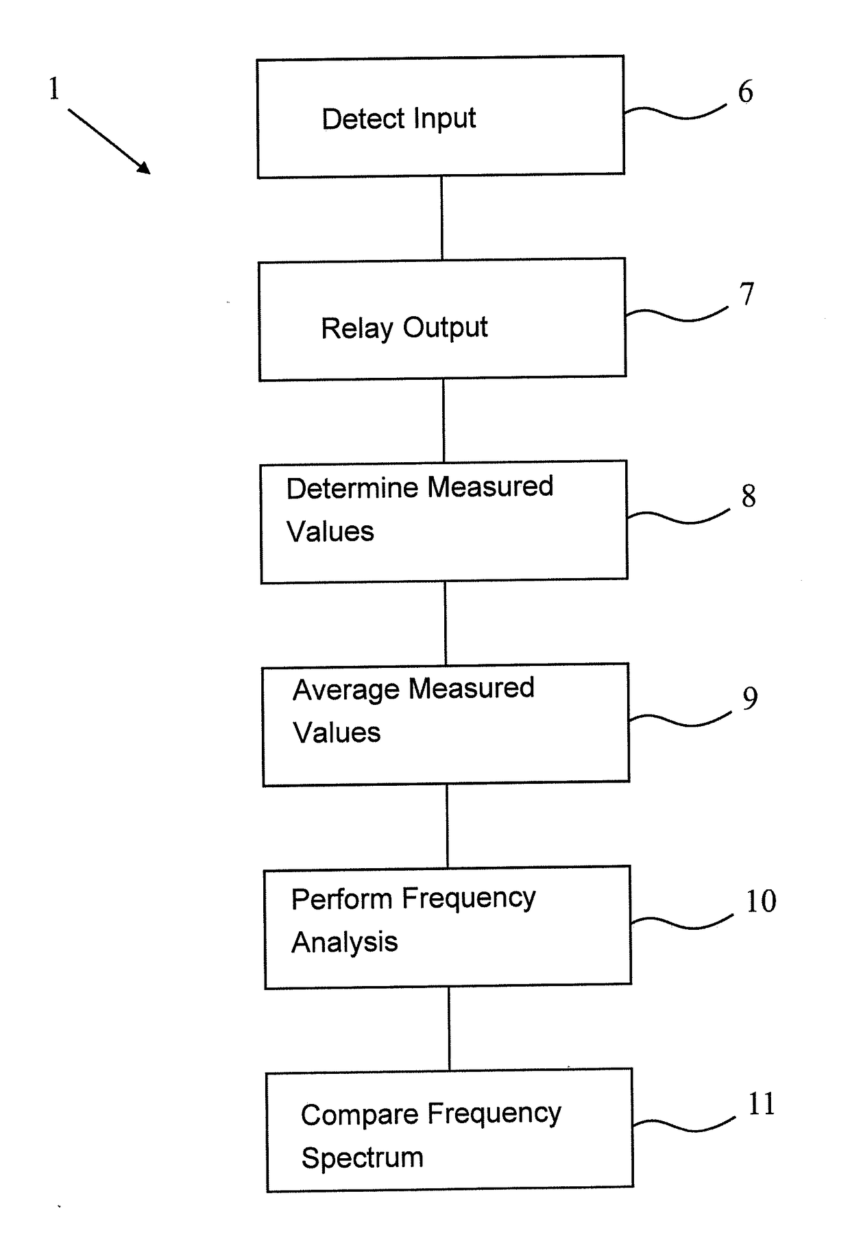
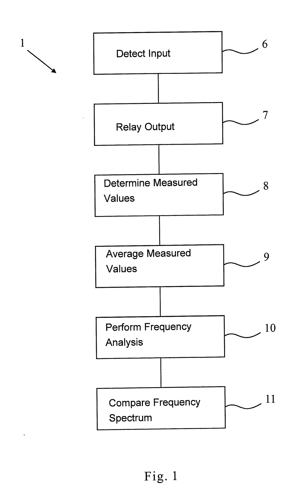
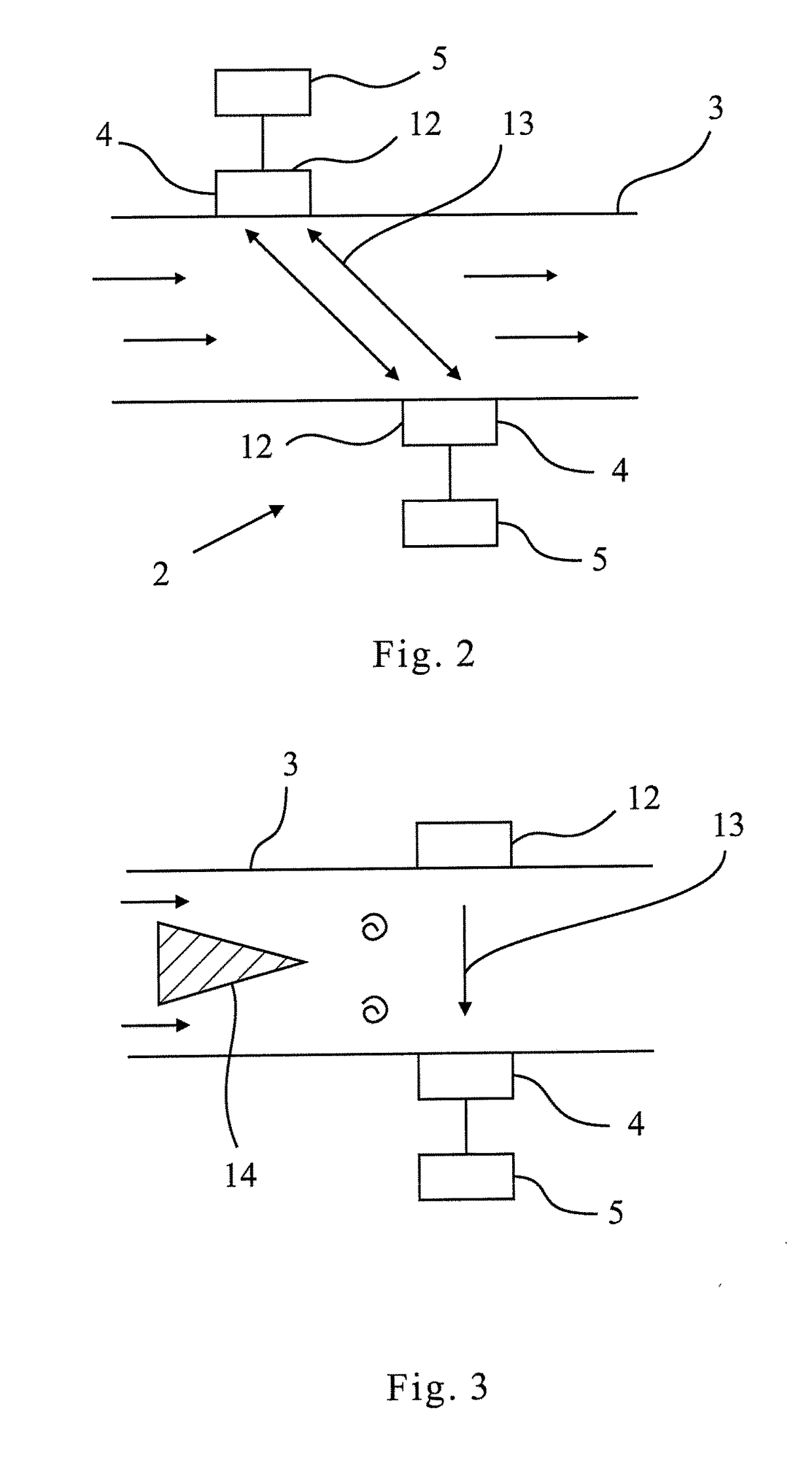
[0029]First of all, the method according to FIG. 1 is described, and with reference being made at the same time to the physical features which are shown in FIGS. 2 to 4.

[0030]A method 1 for detection of pipeline vibrations with a measuring instrument 2 for detecting a measured variable is shown and described in FIG. 1, for the case in which the measuring instrument 2 is attached to a pipeline system 3 through which the medium which is to be measured flows. The measuring instrument 2 has at least one transducer 4 for detection of an input variable and for output of an output variable, and at least one evaluation unit 5.

[0031]In a first step 6, the input variable is detected by the transducer 4 with a scanning rate which has been fixed beforehand. Then, in a next step 7, the transducer 4 relays an output variable which is based on the input variable to the evaluation unit 5. In a next step 8, the evaluation unit 5 determines a measured value of the measured variable from the output va...


PUM


Abstract

A method for detection of pipeline vibrations with a measuring instrument connected to a pipeline system through which a medium to be measured flows, the measuring instrument having at least one transducer for detection of an input variable and for output of an output variable and at least one evaluation unit. The method involves detecting the input variable, relaying of an output variable based on the input variable to the evaluation unit, determinating the measured value of the measured variable from the output variable. Monitoring of the operating state of a system is achieved in that the measured variable characterizes the medium located within the pipeline system, that the sampling rate for detection of the input variable is at least twice as high as the frequency of the pipeline vibration and a frequency analysis of the brief fluctuations of the measured variable is conducted.

Description

BACKGROUND OF THE INVENTIONField of the Invention[0001]The invention relates to a method for detection of pipeline vibrations with a measuring instrument for detecting a measured variable, the measuring instrument being connected to a pipeline system through which the medium which is to be measured flows, and the measuring instrument having at least one transducer for detection of an input variable and for output of an output variable and at least one evaluation unit, comprising the following method steps: detection of the input variable by the transducer, relay of an output variable based on the input variable to the evaluation unit, determination of the measured variable from the output variable by the evaluation unit.Description of Related Art[0002]Moreover, the invention relates to a measuring instrument for detection of a measured variable and for attachment to the pipeline system, which instrument is configured such that the medium which is to be measured flows through it, wit...

Claims


Application Information

Patent Timeline
IPC IPC(8): G01F1/66G01H9/00
CPCG01F1/668G01F1/662G01H9/00G01F1/666G01F1/667G01F1/8427G01F1/8472G01F1/3266
Inventor LEMKE, LARS
Owner KROHNE MESSTECHNICK GMBH & CO KG
Why Eureka
Try Eureka