System and method for traction control

a technology of traction control and system, applied in the direction of control system, vehicle components, propulsion unit safety devices, etc., can solve the problems of wheel slip, wheel slip, potential problems, etc., to reduce vehicle speed, increase or maximize tractive effort, and slow the vehicle

Active Publication Date: 2017-11-23
GE GLOBAL SOURCING LLC
View PDF8 Cites 8 Cited by
  • Summary
  • Abstract
  • Description
  • Claims
  • Application Information

AI Technical Summary

Benefits of technology

[0011]In an embodiment, a wheeled vehicle includes a body, a braking system, a traction motor, a sensor, and a controller. The body includes a plurality of wheels that allow the wheeled vehicle to traverse a route surface. The braking system provides a braking force to a wheel to slow the vehicle and reduce the vehicle speed. The traction motor is operatively connected to the wheel. The sensor detects sliding of the wheel. The controller communicates with the braking system, the traction motor, and the sensor. When the sensor detects sliding of the wheel, the controller may adapt the traction motor to apply a slide reducing force to the wheel in the motoring direction such that the rotational speed of the wheel is limited to a specified creep level during the period of time that the applied braking force exceeds the friction available at the wheel contact surface. That is, motoring force from the traction motor is applied and regulated by the controller such that a rotational speed of the wheel is controlled to substantially match the vehicle speed, and thus to increase or maximize tractive effort, and reduce the rotational speed of the wheel (and the vehicle speed) at a rate that reduces sliding, and increases adhesion. Increasing tractive effort allows the actual vehicle speed to attain the desired vehicle speed in a minimized or determined period of time.

Problems solved by technology

However, when an acceleration force that exceeds the wheel-contact-surface frictional force is applied to a wheel, the wheel may slip in relation to the traversed surface.
Wheel slip occurs when the wheel contact area does not track the traversed surface.
Wheel slip may be potentially problematic as the sliding or spinning of wheels along the traversed surface may cause excessive wear, flat spots and / or other types of damage to a wheel or the traversed surface.
For example, in a full wheel slide, a high amount of abrasive and thermal energy is applied at a singular wheel tread location that may cause flat spots and / or other types of damage to a wheel.
In particular, the high temperatures created between a sliding and / or spinning wheel and the traversed surface can cause spalling, i.e., a transformation of a thin surface layer of the wheel.
Additionally, wheel slide can reduce the ability of an operator, e.g. human and / or machine, to control / drive the wheeled vehicle.
Aggressive application of accelerating forces on a wheel by an operator may increase the chance that wheel slide will occur.
Operators, however, are not always aware that they are aggressively applying an excessive accelerating force to a wheel.
Such braking may increase the wear on the wheels resulting in reduced wheel service life and increased operational costs of the wheeled vehicle and potential damage to the surface which contact the wheel.
Moreover, the design of certain frictional braking systems is such that an operator's ability to arrest and / or control a wheel slide is limited.
Further, current automatic wheel slide protection technologies, such as traditional antilock brakes, have limited potential due to slow responsiveness inherent in the mechanical design of modern braking systems, e.g., a pneumatic braking system in which compressible fluid and substantial control volumes often result in slow responses to changes in frictional braking forces.
Such systems, however, do not use propulsion forces to limit wheel slides that are caused by excessive friction brake application.

Method used


Image

  • System and method for traction control
  • System and method for traction control
  • System and method for traction control

Examples


Embodiment Construction

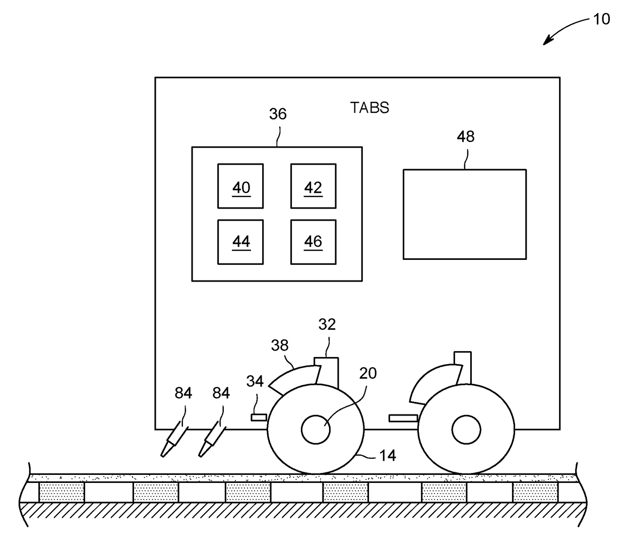
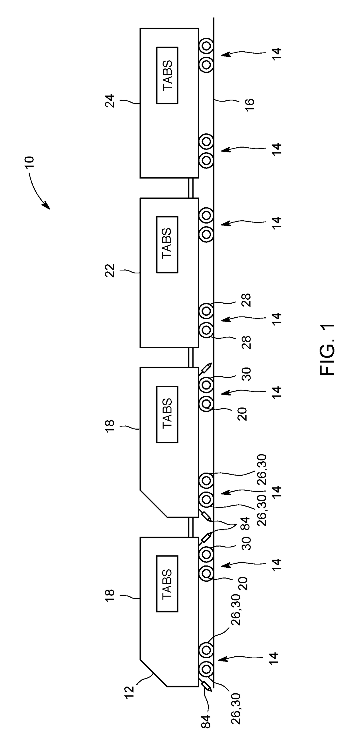
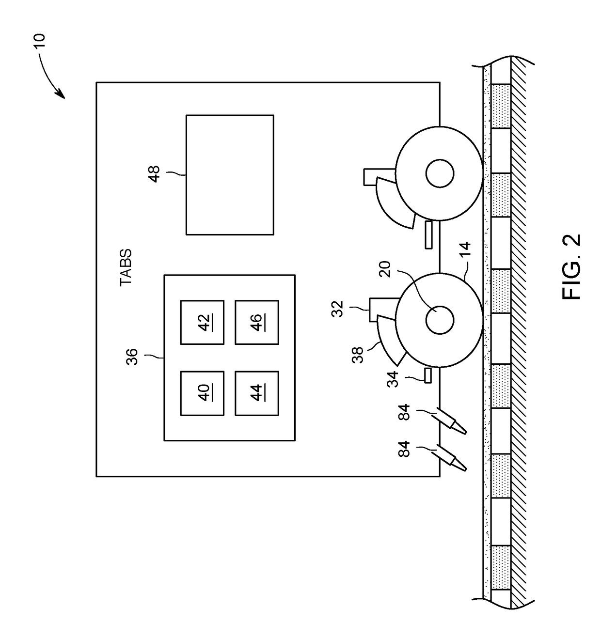
[0017]Embodiments of the invention relate to vehicle control. Certain embodiments relate to systems and methods for traction control in a wheeled vehicle having traction motors. For example, in an embodiment, a system includes a traction motor, a sensor, and a controller. The traction motor may operatively connect to a wheel of a wheeled vehicle. The sensor may detect sliding of the wheel. The controller communicates with the sensor and the traction motor. The controller applies a slide reducing force to the wheel via the traction motor when the sensor detects sliding of the wheel.

[0018]In exemplary instances, a traversed surface, route surface, and / or some other surface can be a metal rail, pavement, earth and / or any other type of surface over which a wheeled vehicle may traverse / move across as it travels along a route. Rail vehicle can be a locomotive, switcher, shunter, and the like and includes both freight haulage and passenger locomotives, which themselves may be diesel electr...


PUM


Abstract

A system includes a sensor and a controller. The sensor is configured to detect sliding of a wheel of a vehicle. The controller is configured to communicate with the sensor and a traction motor operatively connected to the wheel such that the traction motor selectively applies forces in at least one direction to the wheel during operation. The controller is further configured to direct the traction motor to apply a motoring slide reducing force to the wheel when the sensor detects sliding of the wheel resulting from a frictional braking force.

Description

BACKGROUNDTechnical Field[0001]Embodiments of the invention relate to traction control in wheeled vehicles.Discussion of Art[0002]Some types of vehicles may use wheels to traverse a surface. In such vehicles, a wheel may have a surface formed by the exterior of the circumference of the wheel, known as the contact surface that contacts with the traversed surface. The part of the contact surface that is in contact with the traversed surface at any particular moment is known as the contact area. A frictional force exists between the contact area and the traversed surface referred to as the wheel-contact-surface frictional force.[0003]Certain wheeled vehicles control their speed by applying accelerating forces, e.g., propulsion and braking forces, to one or more wheels. However, when an acceleration force that exceeds the wheel-contact-surface frictional force is applied to a wheel, the wheel may slip in relation to the traversed surface. Wheel slip occurs when the wheel contact area do...

Claims


Application Information

Patent Timeline
Patent Type & Authority Applications(United States)
IPC IPC(8): B60T8/17B60T8/171B60T8/175
CPCB60T8/1705B60T2270/20B60T8/171B60T8/175
Inventor KUMAR, AJITH KUTTANNAIRWORDEN, BRET DWAYNELOVERCHECK, GLENNSINGH, DHARMDEOZHANG, JINGJUNMCGARRY, JEREMY
Owner GE GLOBAL SOURCING LLC
Why Eureka
Try Eureka