
Outboard motor

Active Publication Date: 2017-11-23
SUZUKI MOTOR CO LTD
View PDF2 Cites 0 Cited by
  • Summary
  • Abstract
  • Description
  • Claims
  • Application Information

AI Technical Summary

Benefits of technology

The technical effect of this patent is to reduce the formation of cavities around a strut portion.

Problems solved by technology

The cavitation causes erosion, and furthermore, when air bubbles due to the cavitation reach the propeller device, propellers' propulsion efficiency decreases.

Method used


Image

  • Outboard motor
  • Outboard motor
  • Outboard motor

Examples


working example

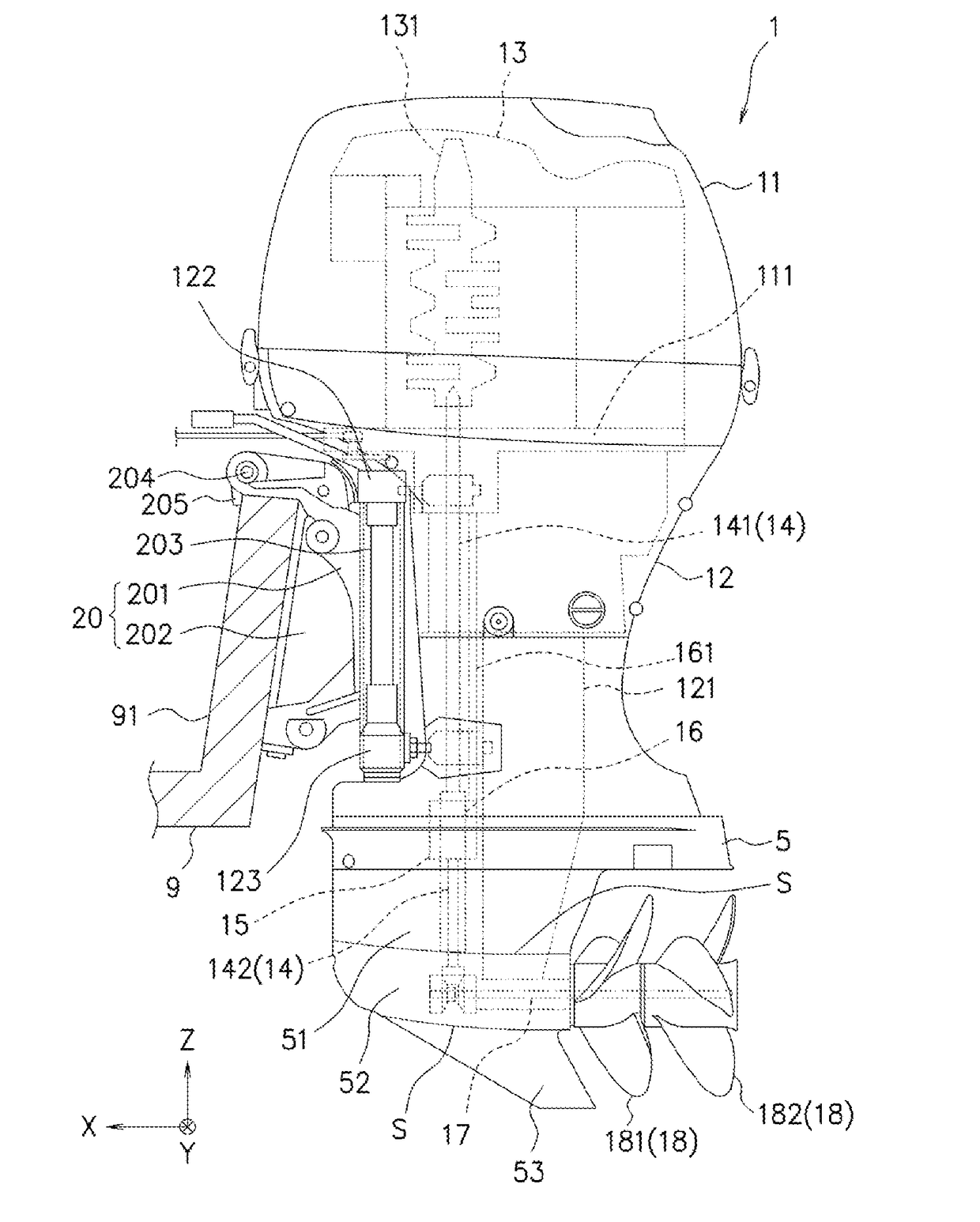
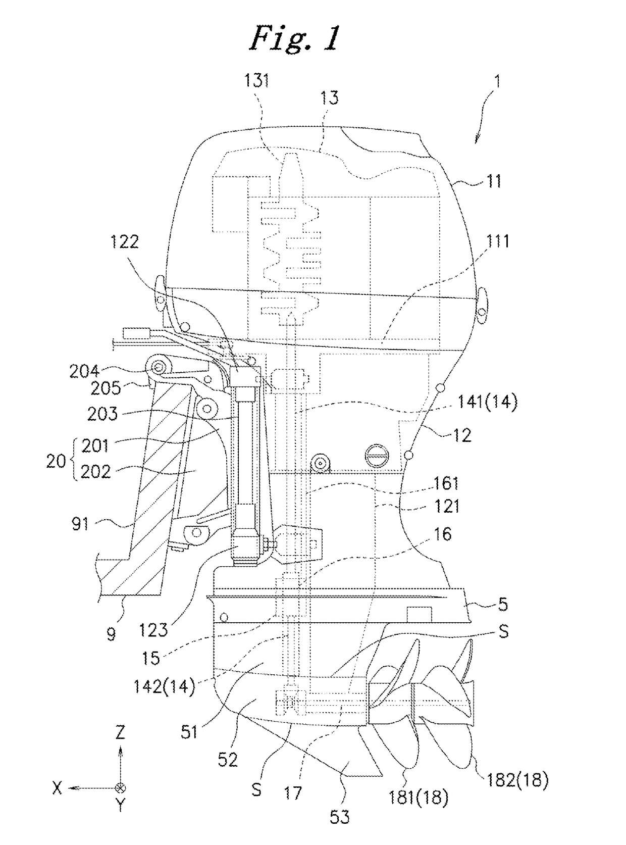
[0017]The following describes embodiments of the present invention in detail with reference to the drawings. The embodiments of the present invention employ an outboard motor that includes a contra-rotating propeller as an example. In the respective drawings, respective directions of the outboard motor are indicated with a three-dimensional coordinate system. In the embodiments of the present invention, an X-axis direction indicates a front-rear direction of the outboard motor, a Y-axis direction indicates a right-left direction, and a Z-axis direction indicates an up-down direction. A line S and a line T in the respective drawings are lines for the explanation of a shape of a gear housing of the outboard motor, and actually invisible (not existing) lines.

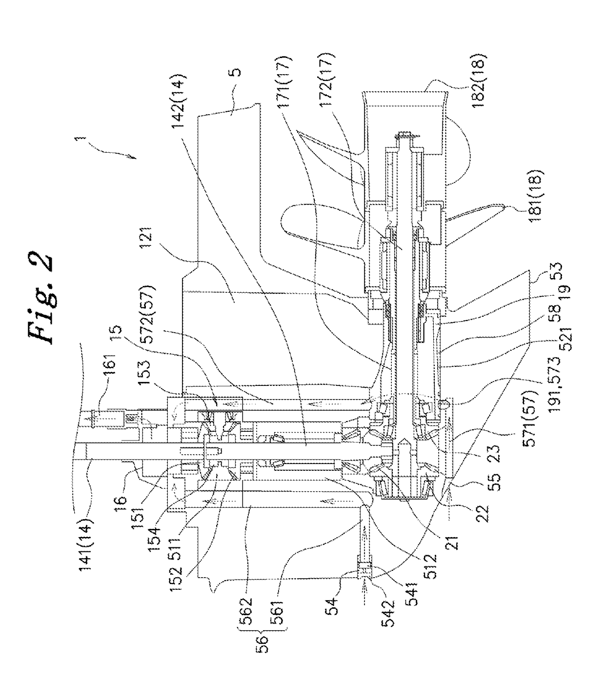
[0018]First, a description will be given of an exemplary configuration of an outboard motor 1 with reference to FIG. 1 and FIG. 2. FIG. 1 is a left side view schematically illustrating an exemplary configuration of the outboard mot...


PUM


Abstract

An outboard motor includes a gear housing configured to rotatably house a propeller shaft that transmits a rotative power output from an engine to a propeller device. The gear housing includes a torpedo shape portion and a strut portion. The torpedo shape portion has a shape tapered toward a front side, and a shape biased upward toward the front side. The strut portion is disposed on an upper side of the torpedo shape portion. An outer peripheral surface of the torpedo shape portion is smoothly coupled to an outer peripheral surface of the strut portion via first to third curved surfaces. The first to third curved surfaces are each a curved surface inclined rearward and downward, a curved surface parallel to a front-rear direction, or a curved surface constituted of a part inclined rearward and downward and a part parallel to the front-rear direction.

Description

CROSS-REFERENCE TO RELATED APPLICATIONS[0001]This application is based upon and claims the benefit of priority of the prior Japanese Patent Application No. 2016-101297, filed on May 20, 2016, the entire contents of which are incorporated herein by reference.BACKGROUND OF THE INVENTIONField of the Invention[0002]The present invention relates to an outboard motor.Description of the Related Art[0003]A gear housing of an outboard motor includes a strut portion that rotatably houses a lower portion of a drive shaft, and a torpedo shape portion that rotatably houses a propeller shaft and is disposed on a lower side of the strut portion. Then, the gear housing has a rear side on which a propeller device is rotatably disposed. The strut portion has a width maximum on proximity of a center portion in a front-rear direction and decreased toward a front side and a rear side. This causes a flow rate of water around the strut portion during navigation to be increased on the part with the maximum...

Claims


Application Information

Patent Timeline
IPC IPC(8): B63H20/34B63H20/28B63H20/32
CPCB63H20/34B63H2020/323B63H20/28B63H20/32B63H20/14B63H20/24B63H20/285B63H2020/006
Inventor SUGIYAMA, SHUICHIDAIKOKU, KEISUKE
Owner SUZUKI MOTOR CO LTD
Features
  • Generate Ideas
  • Intellectual Property
  • Life Sciences
  • Materials
  • Tech Scout
  • Unparalleled Data Quality
  • Higher Quality Content
  • 60% Fewer Hallucinations
Learn More