Folding wing tip and rotating locking member

a technology of locking member and folding wing tip, which is applied in the direction of rotorcraft, wing adjustment, airflow influencer, etc., can solve the problems of conventional locking mechanism not providing the secure fastening required for folding wing tip, and the maximum aircraft span is effectively limited, so as to reduce or prevent the locking pin from hogging or bending under load, and increase the strength of the locking arrangement

Active Publication Date: 2017-11-23
AIRBUS OPERATIONS LTD
View PDF5 Cites 4 Cited by
  • Summary
  • Abstract
  • Description
  • Claims
  • Application Information

AI Technical Summary

Benefits of technology

[0008]The rotatable locking member may be associated with a secondary locking mechanism, the secondary locking mechanism arranged to prevent rotation of the rotatable locking member when the rotatable locking member is in the locked position.
[0009]The rotatable locking member may be located within a lock housing. The lock housing may be fixed relative to the wing or wing tip device and arranged to allow rotational movement of the rotating locking member within the housing. The housing may comprise a landing, the landing arranged to contact the locking pin when

Problems solved by technology

However, the maximum aircraft span is effectively limited by airport operating rules which govern various clearances required when manoeuvring around the airport (such as the span a

Method used


Image

  • Folding wing tip and rotating locking member
  • Folding wing tip and rotating locking member
  • Folding wing tip and rotating locking member

Examples


Embodiment Construction

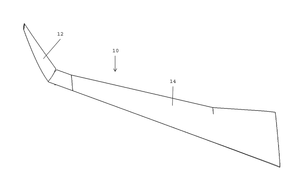
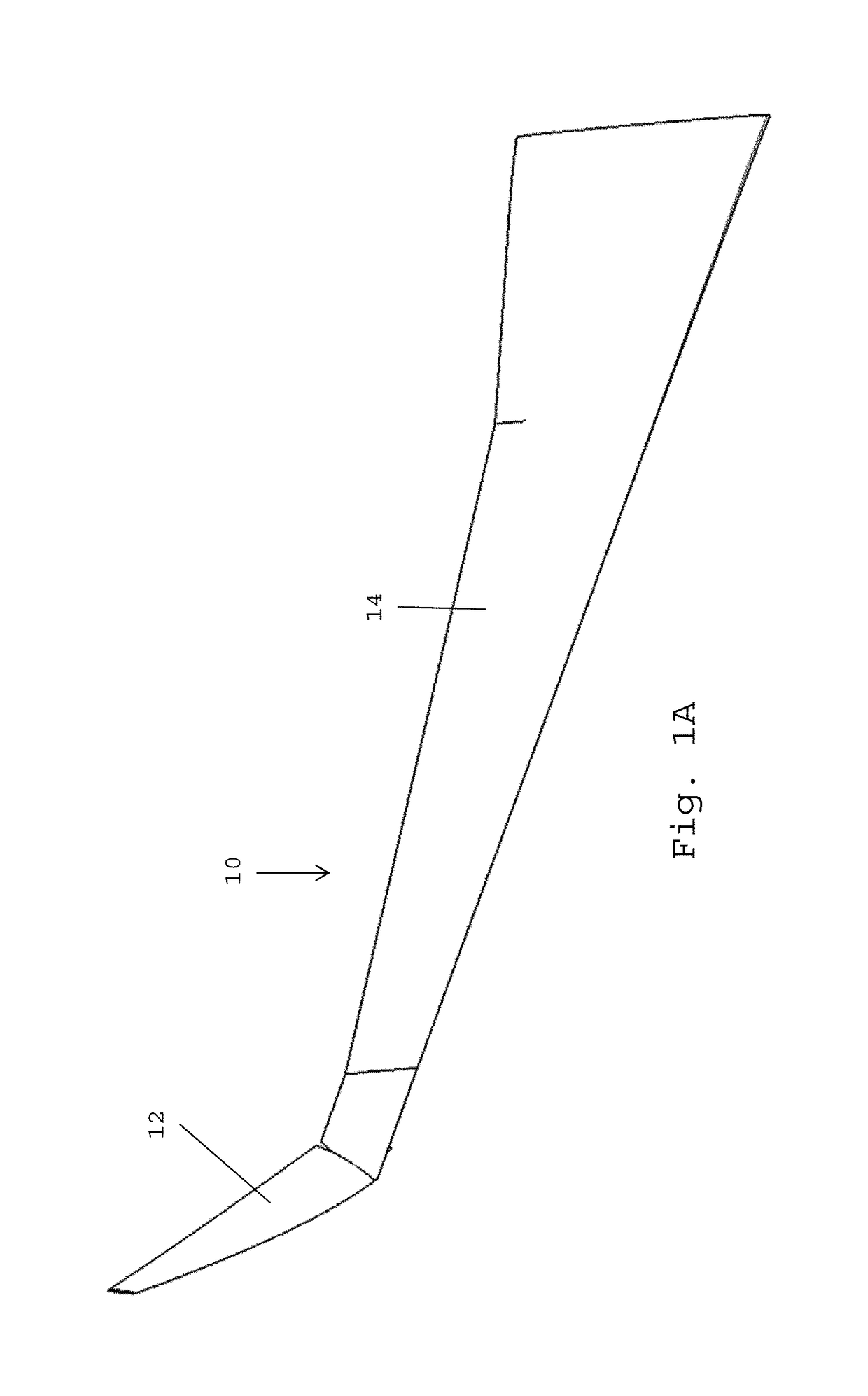
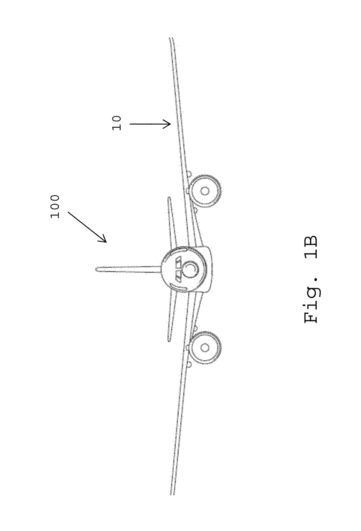
[0025]FIG. 1A shows a wing 10 comprising a wing tip device 12 and a fixed wing 14. FIG. 1B shows an aircraft 100 comprising the wing 10. The wing tip device 12 is configurable between: (i) a locked flight configuration for use during flight, as shown in FIG. 1B and (ii) a ground configuration for use during ground-based operations, as shown in FIG. 1A, in which ground configuration the wing tip device 12 is moved away from the locked flight configuration such that the span of the aircraft wing 10 is reduced.

[0026]FIG. 2 shows a locking mechanism 20 comprising a locking pin 22 and a rotatable locking member 24. The locking pin 22 may be associated with a wing tip device 12, and the locking mechanism 20 associated with the wing 10, or vice versa. The locking pin 22 comprises a cylinder with a central longitudinal axis A. The rotatable locking member 24 comprises a U-shaped receiving portion 26, which is shaped to receive the locking pin 22. The receiving portion 26 has a wide mouth to...


PUM


Abstract

A rotatable locking member for locking an aircraft wing with a movable wing tip device. The rotatable locking member including a U-shaped receiving portion arranged such that in an unlocked position the locking pin may be moved into and out of the U-shaped receiving portion, and in a locked position the locking pin is not able to be moved out of the U-shaped receiving portion, and the rotatable locking member is configured to be moved between the unlocked and locked position by rotational movement around the longitudinal central axis of the locking pin.

Description

BACKGROUND OF THE INVENTION[0001]There is a trend towards increasingly large passenger aircraft, for which it is desirable to have correspondingly large wing spans. However, the maximum aircraft span is effectively limited by airport operating rules which govern various clearances required when manoeuvring around the airport (such as the span and / or ground clearance required for gate entry and safe taxiway usage).[0002]Therefore, folding wing tip devices have been introduced into passenger aircraft, where a wing tip device is movable between a flight configuration for use during flight, and a ground configuration for use during ground-based operations. In the ground configuration, the wing tip device is moved away from the flight configuration such that the span of the aircraft wing is reduced, thereby allowing use of existing gates and safe taxiway usage.[0003]In order to securely fasten the folding wing tip device in the flight configuration, one or more locking mechanisms must be...

Claims


Application Information

Patent Timeline
IPC IPC(8): B64C3/56
CPCB64C3/56B64C23/072Y02T50/10B64C27/50
Inventor WILDMAN, ERICHARDING, MATTHEW
Owner AIRBUS OPERATIONS LTD
Why Eureka
Try Eureka