Rod de-tensioning device and methods of operating the same

Active Publication Date: 2017-11-23
FDH INFRASTRUCTURE SERVICES LLC
View PDF4 Cites 2 Cited by
  • Summary
  • Abstract
  • Description
  • Claims
  • Application Information

AI Technical Summary

Benefits of technology

[0015]Another embodiment of the present disclosure includes a method of detensioning a rod, the method including removably attaching a gripping unit removal device on a gripping unit where the gripping unit engages a rod, positioning a chair frame on the rod over a periphery of the gripping unit, positioning a rod tensioning unit on the rod with a first end of the rod tensioning unit being in contact with a surface of the chair frame, applying a first force to the rod tensioning unit, positioning

Problems solved by technology

For large structures, such as dams, a large amount of tension (typically 60% or more of its ultimate strength) is applied to the rods creating a potentially dangerous situation.
Increased tension, in addition to long-term environmental stresses in the rods creates a dangerous situation where the rods may fail in a brittle and abrupt manner before the end of life expectancy date.
However, even wi

Method used


Image

  • Rod de-tensioning device and methods of operating the same
  • Rod de-tensioning device and methods of operating the same
  • Rod de-tensioning device and methods of operating the same

Examples


Embodiment Construction

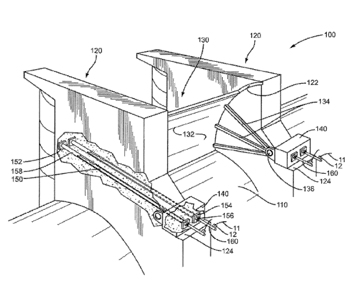
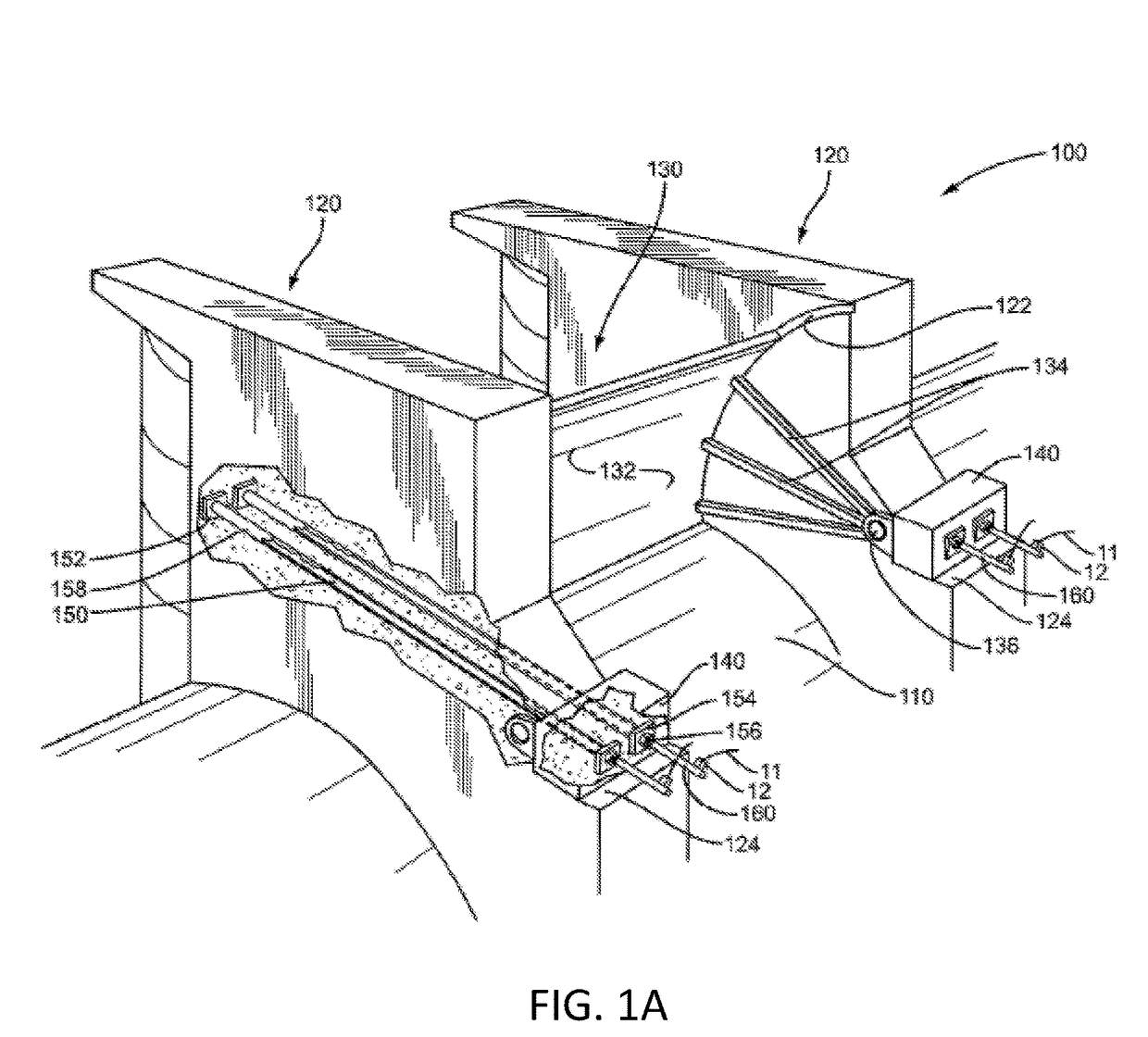
[0035]FIG. 1A depicts a dam 100 that includes a spillway 110 defined between two piers 120. Mounted between piers 120 is Tainter gate 130 comprised of a curved panel 132 supported on radial arms 134. Radial arms 134 converge at trunnion pin 136 that is supported at a rotational pivot by trunnion girders 140. The trunnion girders 140 are separate from the piers 120 and are secured to the piers 120 by rods 150. Sides of curved panel 132 may slide through and engage with curved leak limiting slots 122 in side faces of piers 120. It is to be appreciated that a water reservoir is on the convex or upstream side of curved panel 132. When gate 130 is closed the panel is in the lower position as shown in FIG. 1A and water is prevented from flowing downstream over the dam by curved panel 132. When gate 130 is opened by rotating radial arm structure 134 about trunnion pin 136, water from the reservoir is permitted to flow under panel 132, over spillway 110, and downstream from dam 100.

[0036]Tr...


PUM


Abstract

A rod detensioning unit including a gripping unit removal device that engages a gripping unit on a rod, a chair frame configured to engage a rod, a rod tensioning unit that applies tension to an external portion of the rod to remove load from the gripping unit, a load cell unit that measures a tension level applied to the rod by the tensioning unit, a plate gripping unit that engages the rod and secures the chair frame, rod tensioning unit, load cell and plate gripping unit to the rod, a drive unit that engages the gripping unit removal device, and an extension unit affixed to the external portion of the rod when the original external rod length is too short to accommodate the de-tensioning unit.

Description

CROSS-REFERENCE TO RELATED APPLICATIONS[0001]The present disclosure claims priority to U.S. Provisional Patent App. No. 62 / 335,362, entitled “ROD DE-TENSIONING DEVICE AND METHODS OF OPERATING THE SAME” filed on May 12, 2016, which is incorporated by reference herein in its entirety.BACKGROUND OF THE INVENTION[0002]Post-tensioned trunnion anchor rods are used to secure large devices, such as gates on dams, to structures. To firmly secure the devices to the structure, tension is applied to the trunnion rods, and the individual rods are locked off to maintain the tension load within the rod. See, U.S. Pat. No. 2,705,871 to Kenigsberg and U.S. Pat. No. 2,871,664 to Dobson. For large structures, such as dams, a large amount of tension (typically 60% or more of its ultimate strength) is applied to the rods creating a potentially dangerous situation. At least 100-200 dams in the United States use post-tensioned trunnion rods for gate anchorages. Trunnion rods are predominately made of meta...

Claims


Application Information

Patent Timeline
IPC IPC(8): E04G21/12E04C5/12G01L5/04
CPCE04G21/121G01L5/042E04C5/122
Inventor LINDYBERG, ROBERTKHAN, RAKESHKARSHENAS, AFSHINFUQUA, BRENNONFERGUSON, TRAVIS
Owner FDH INFRASTRUCTURE SERVICES LLC
Why Eureka
Try Eureka