Gas powered gun and a pressure tube for a gas powered gun

a gas powered gun and pressure tube technology, applied in the field of gas powered guns, can solve the problems of time-consuming, and achieve the effect of weak biasing of the member

Inactive Publication Date: 2017-11-23
FX AIRGUNS AB
View PDF5 Cites 1 Cited by
  • Summary
  • Abstract
  • Description
  • Claims
  • Application Information

AI Technical Summary

Benefits of technology

[0034]With this design, the fluid connection can be effectively sealed by the piston making contact with the valve seat and closing the first opening. This in turn requires a relatively small pressure on the piston to close the fluid connection, enabling a relatively weak biasing member.
[0035]As an example, the first opening may be located centrally on an upper surface of the valve seat, and the passage-way through teh piston may have an opening into the intermediate chamber at a distance from a central axis of the piston. This makes it possible for the central surface of the puiston to close the first opening.

Problems solved by technology

This is time consuming and usually requires a test rig in order to get exact values.

Method used


Image

  • Gas powered gun and a pressure tube for a gas powered gun
  • Gas powered gun and a pressure tube for a gas powered gun
  • Gas powered gun and a pressure tube for a gas powered gun

Examples


Embodiment Construction

[0057]Embodiments of the present disclosure will be described in more detail in the following with reference to the accompanying drawings.

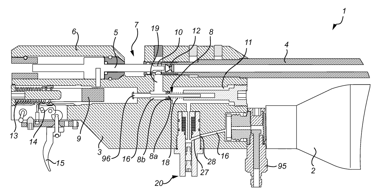
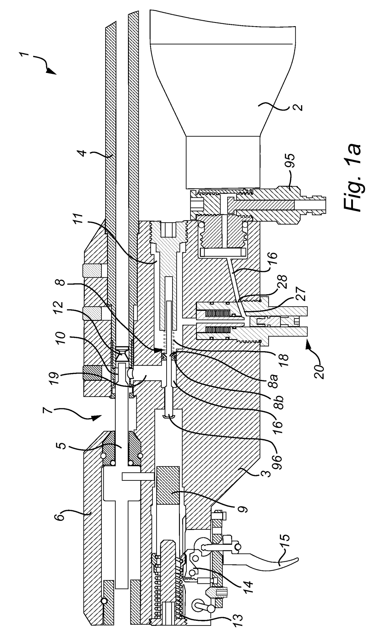
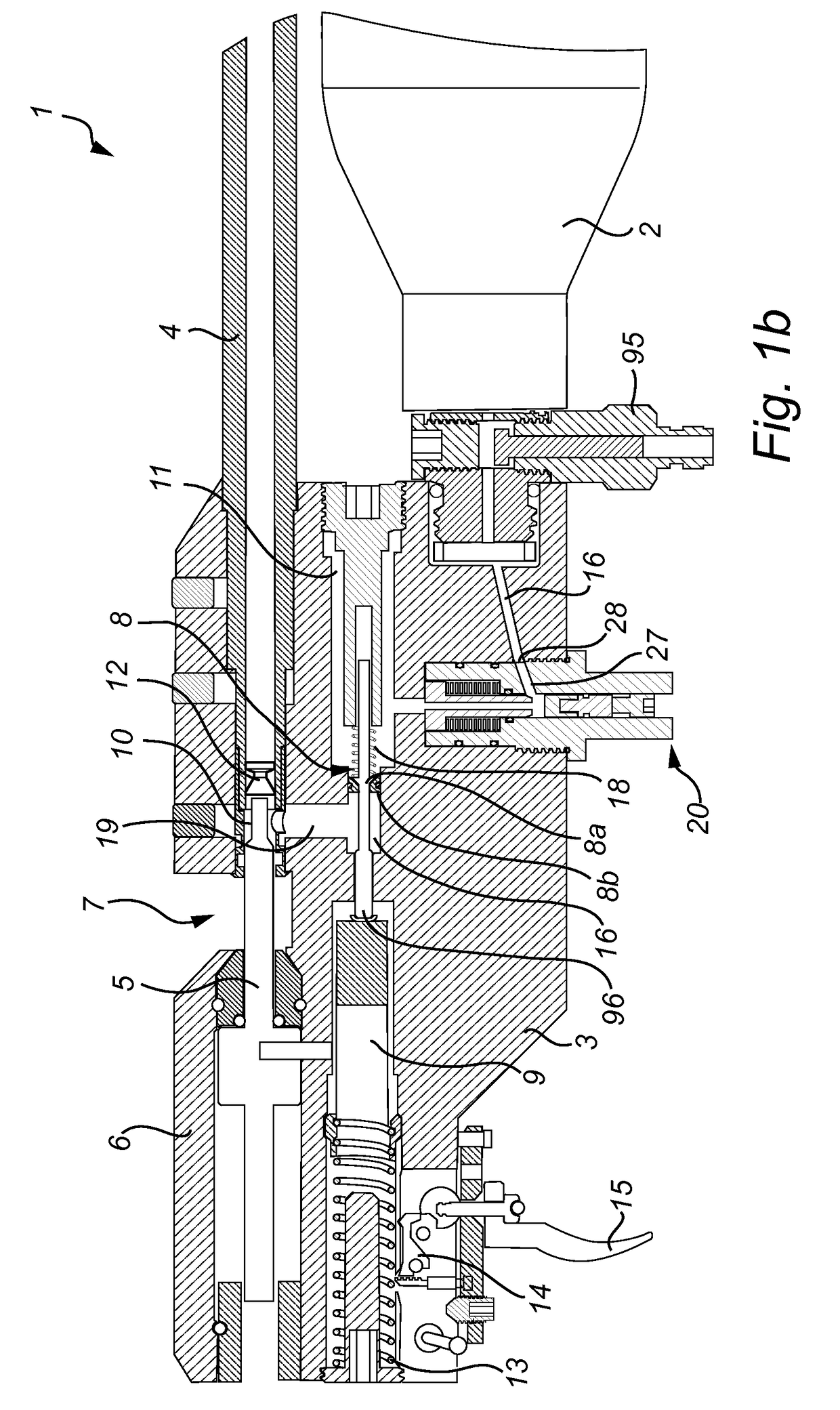
[0058]FIGS. 1a and 1b shows a gas powered gun 1. The gun 1 is of the kind where a bottle 2 of compressed air or other gas is fitted to the body 3 of the gun 1. The compressed gas is fed to a pressure chamber 11 and when the trigger 15 of the gun 1 is pulled, the compressed air is forwarded to a space 10 behind a bullet 12 which fires the bullet 12. In more detail, the bottle 2 is connected to the gun 1 at the front. A connector 95 is arranged between the bottle 2 and the gun 1 and it is used to fill the bottle 2 with gas. The gun 1 also comprises a gas regulator 20. A passage 16 in the gun body 3 forwards the gas from the bottle 2 into the regulator 20, which regulates the gas pressure in the pressure chamber 11. The gun 1 further comprises a barrel 4, and a feeder pin 5 slidably arranged in a housing 6 behind the barrel 4. In a space between the ...


PUM


Abstract

A gas powered gun and a pressure tube for a gas powered gun each comprises a gas regulator between a pressure chamber and a source of compressed gas. The gas regulator comprises a body forming first and second cylindrical portions connected to each other. The first cylindrical portion is in fluid connection with the pressure chamber. A piston is mounted for sliding movement in the first and second cylindrical portions. A valve seat is in the second cylindrical portion. An intermediate chamber is in the second cylindrical portion between the piston and the valve seat and in fluid connection with the source of compressed gas. A passageway through the piston connects the pressure chamber with the intermediate chamber. A biasing member presses the piston resiliently away from the valve seat. A valve seat adjusting mechanism is accessible to a user for adjusting a position of the valve seat.

Description

TECHNICAL FIELD[0001]The present disclosure relates to a gas powered gun, comprising a pressure chamber and a gas regulator, which is arranged between said pressure chamber and a source of compressed gas. It also relates to a pressure tube for a gas powered gun, comprising a pressure chamber and a gas regulator, which is arranged between said pressure chamber and a source of compressed gas.TECHNICAL BACKGROUND[0002]Air guns are designed to have a controlled amount of high pressure air in a pressure chamber which is forwarded into the gun barrel behind a pellet in order to projectile the same out of the barrel. The air or the gas is usually provided from a reservoir of compressed gas at high pressure. In order to present the air or the gas to the pellet at a constant pressure a regulator can be used.[0003]A regulator is a mechanical device, i.e. a valve that controls the air pressure and the volume available to the fire valve of a pre-charged airgun. This means that the pressure is a...

Claims


Application Information

Patent Timeline
Patent Type & Authority Applications(United States)
IPC IPC(8): F41B11/723F41B11/724F41B11/62
CPCF41B11/723F41B11/62F41B11/724
Inventor AXELSSON, FREDRIK
Owner FX AIRGUNS AB
Why Eureka
Try Eureka