Display apparatus with a multi-layer absorption, conduction and protection film

a protective film and absorption technology, applied in the direction of discharge tube luminescnet screen, electrical connection of cathode-ray/electron beam tube, instruments, etc., can solve the problems of undesirable influence of optical interference effect, deterioration of performance as anti-reflection film, and insufficient development of high-definition braun tube. , to achieve the effect of reducing the contribution to the interference of light, reducing the anti-reflection

Inactive Publication Date: 2006-01-31
PANASONIC LIQUID CRYSTAL DISPLAY CO LTD +1
View PDF15 Cites 1 Cited by
  • Summary
  • Abstract
  • Description
  • Claims
  • Application Information

AI Technical Summary

Benefits of technology

[0007]However, as a result, the refractive index of the film is decreased so as to be smaller than the high refractive index of the original oxide film due to the addition of the coloring material, because the refractive index of the oxide and the refractive index of the coloring material are averaged. Accordingly, with regard to the reflectance curve, the value at the bottom is increased, because the difference between the refractive indexes of the upper and lower layers is decreased.
[0023]Generally, coloring material is decomposed by ultraviolet rays, and the light resistance thereof is weak. Conventionally, pigment group coloring materials having a strong light resistance as a coloring material, but undesirable absorption characteristics, have been used as the coloring material. However, in accordance with the composition of the present invention, dye group coloring materials having desirable absorption characteristics, but weak light resistance, can be used, with the result that a high performance display apparatus having preferable wavelength selective absorption characteristics can be manufactured.

Problems solved by technology

However, the prior efforts described above have proven to be insufficient for development of high definition Braun tube.
When anti-reflection is realized by an optical interference effect, the optical interference effect is undesirably influenced, because the refractive index is varied by an abnormal dispersion of the refractive index of the coloring material.
Therefore, the refractive index curve does not become flat, but exhibits a waviness and an abnormal region to increase the refractive index and so on, and, as a result, the performance as an anti-reflection film is deteriorated.
Therefore, a relationship between the refractive indexes of the upper layer and that of the lower layer are inverted relative to each other, and so the control of the refractive indexes becomes difficult.

Method used


Image

  • Display apparatus with a multi-layer absorption, conduction and protection film
  • Display apparatus with a multi-layer absorption, conduction and protection film
  • Display apparatus with a multi-layer absorption, conduction and protection film

Examples


embodiment 1

(Embodiment 1)

[0032]As an embodiment of the present invention, an example of a Braun tube representing the display apparatus of the invention will be explained.

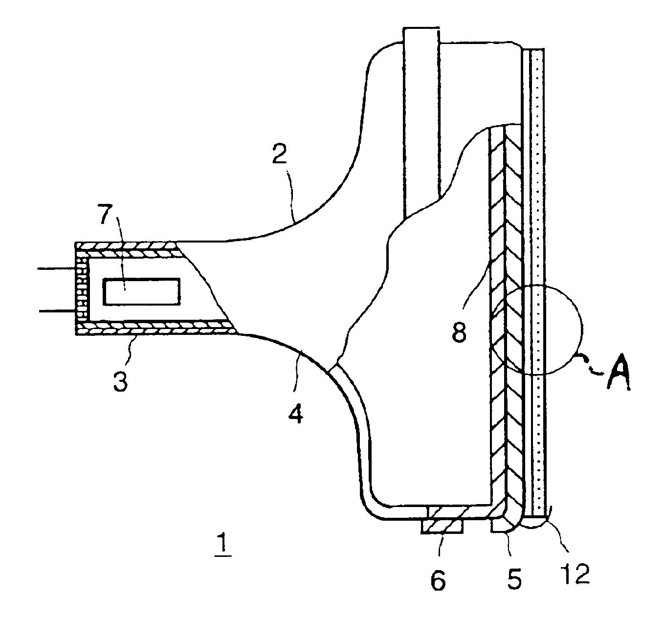
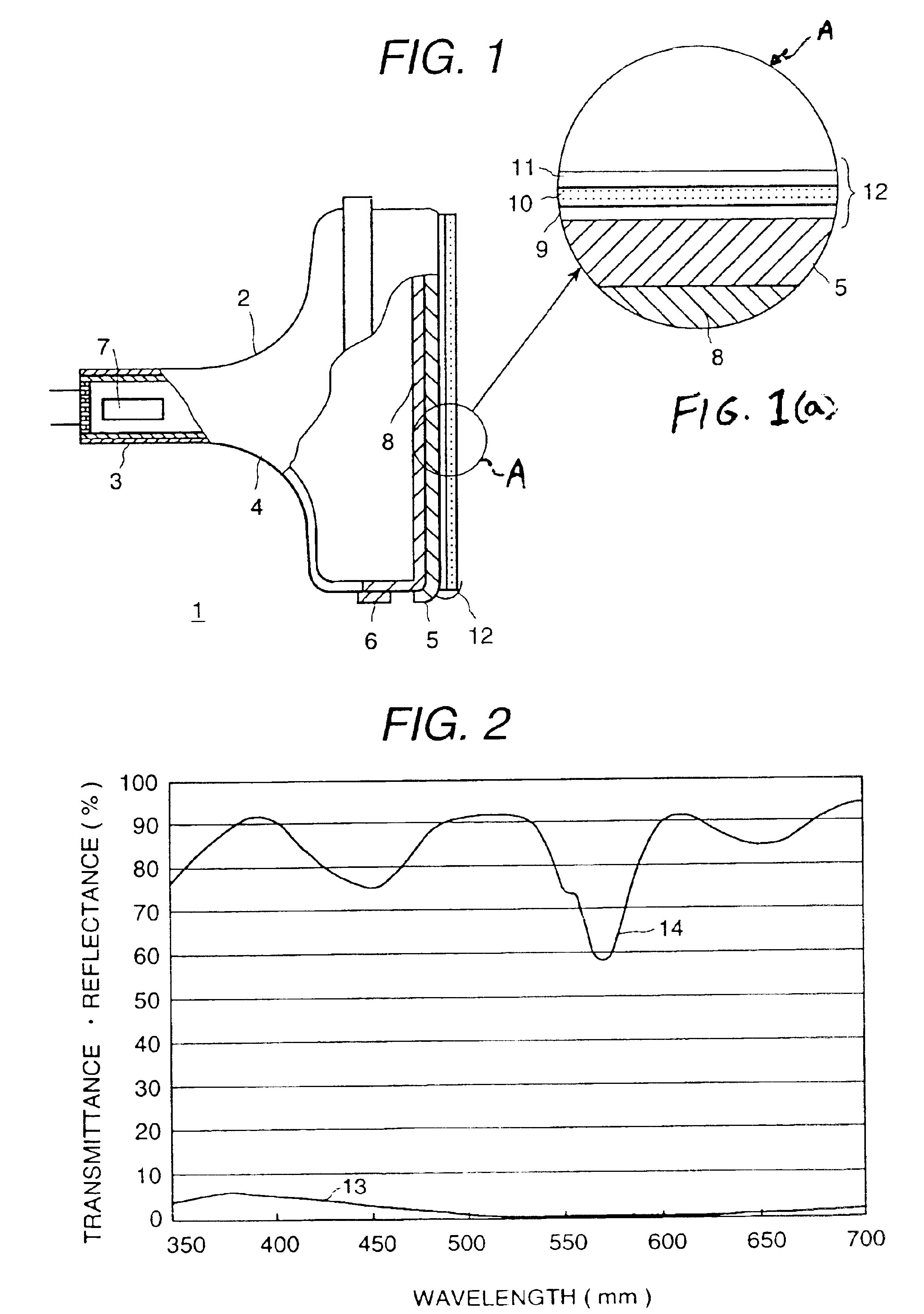
[0033]FIG. 1 is a partially cutaway side view illustrating a Braun tube 1 representing an embodiment of the present invention. FIG. 2 is a graph indicating an observed result relating to the relationship between each of a reflectance (indicated by the curve 13 in the figure) and a transmittance (indicated by the curve 14 in the figure) of the surface treatment film of the Braun tube with respect to the wavelength of light in the present embodiment.

[0034]The high definition Braun tube 1 comprises a housing 2 made of glass, of which the interior is evacuated. The housing 2 comprises a neck 3, a funnel portion 4 which continues from the neck 3, and a face plate 5 sealed by frit glass. The outer peripheral side-wall of the face plate 5 has a metallic tension band 6 wound thereon for anti-explosion. An electron gun 7 for dischargi...

embodiment 2

(Embodiment 2)

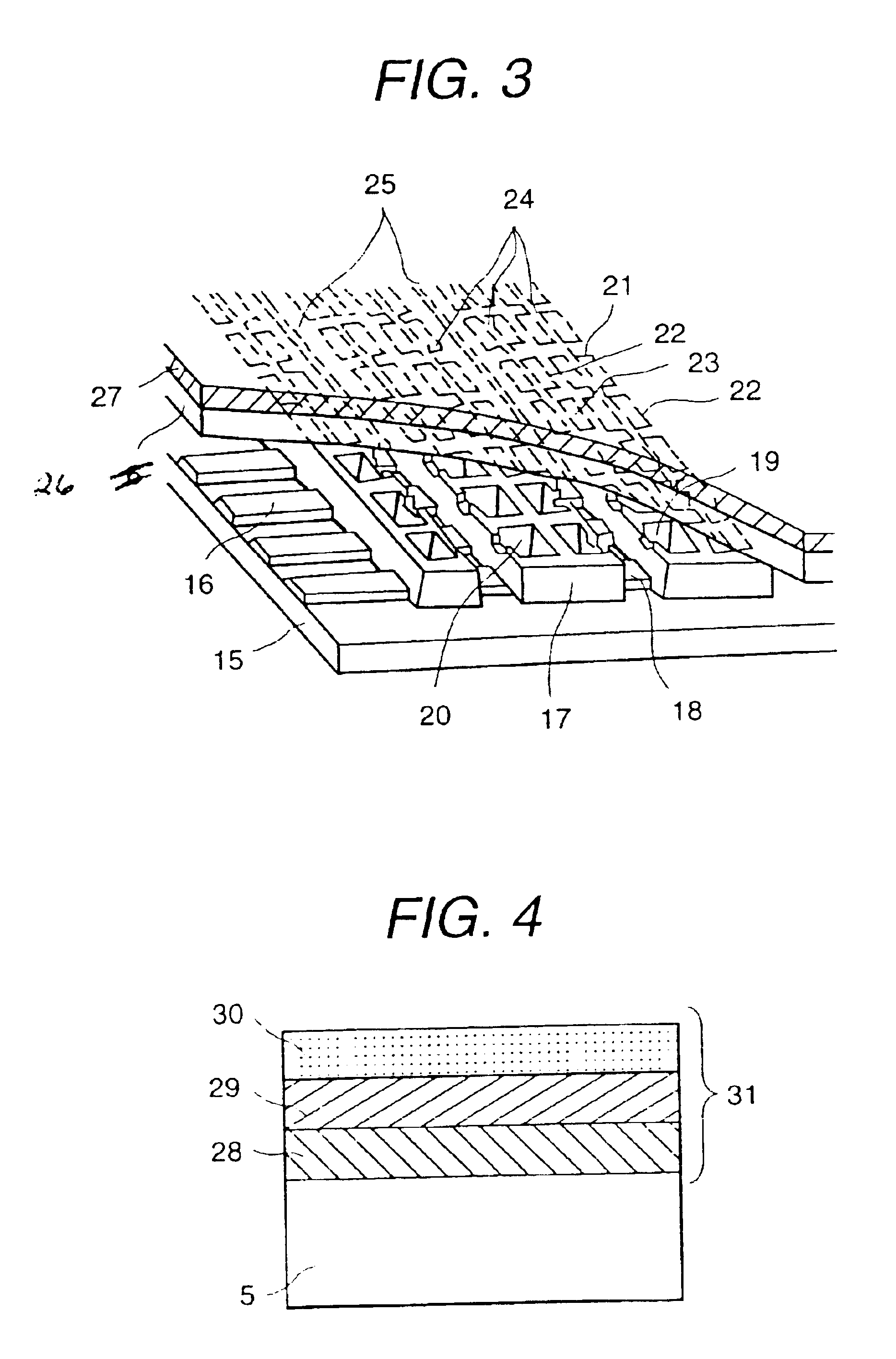
[0051]Next, a film was manufactured, wherein an organic resin was added to the SiO2 film containing coloring material at the lowest layer, as illustrated in FIG. 4. The method of manufacturing the film will be explained by way of example.

[0052]The SiO2 film 28 containing resin and coloring material was formed on a face plate 5 by spin-coating a coating solution, prepared by adding acrylic resin and the coloring material into silica sol, onto a surface of a Braun tube at 160 rpm, followed by drying at 60° C. for 5 minutes. Then, a Ag—Pd film 29 was laminated onto the SiO2 film 28 containing resin and coloring material by applying a Ag—Pd fine particles dispersion solution onto the SiO2 film and spin coating at 160 rpm, followed by drying at 60° C. for 5 minutes. Finally, a SiO2 film 30 was formed on the Ag—Pd film 29 by spin coating a SiO film onto the Ag-Pd film 29 at 160 rpm, and drying the film at 60 C for 5 minutes.

[0053]The composition of the solution prepared by a...

embodiment 3

(Embodiment 3)

[0056]Next, a film was manufactured, wherein ATO fine particles were added to the SiO2 film containing coloring material at the lowest layer, as illustrated in FIG. 5. The method of manufacturing the film will be explained by way of example.

[0057]The SiO2 film 32 containing ATO and a coloring material was formed on a face plate 5 by spin-coating a coating solution, prepared by adding ATO fine particles and the coloring material into silica sol, onto a surface of a Braun tube at 160 rpm, and then drying the solution at 60° C. for 5 minutes. Then, a Ag—Pd film 33 was laminated onto the SiO2 film 32 containing ATO and coloring material by applying a Ag-Pd fine particles dispersion solution onto the SiO2 film performing spin coating at 160 rpm, and drying the film at 60 C for 5 minutes. Finally, a SiO film 34 was formed on the Ag—Pd film 33 by spin coating a SiO2 film onto the Ag—Pd film 33 at 160 rpm, and drying the film at 60 C for 5 minutes.

[0058]The composition of the ...


PUM

PropertyMeasurementUnit
luminous transmittanceaaaaaaaaaa
luminous reflectanceaaaaaaaaaa
resistanceaaaaaaaaaa

Abstract

A high definition display apparatus having a wavelength selective absorption effect and an anti-static and anti-reflection effect is provided by thin films having a low resistance and a high refractive index. The high definition display apparatus has an anti-static and anti-reflection film composed of laminated oxide or metallic thin films, wherein at least three layers of oxide or metallic films having different reflectance from each other are laminated onto the front surf ace of the display apparatus, and the laminated films are composed such that an absorbing film containing coloring material is arranged under a high reflectance film as seen from the outer surface of the laminated films.

Description

BACKGROUND OF THE INVENTION[0001]In order to obtain a display apparatus which is capable of producing a high definition display, various surface treatment films have been formed on the surface of the display plane of the display apparatus. For instance, the use of an anti-static anti-reflection film has been proposed, as disclosed in JP-A-4-334853 (1992). Furthermore, the use of a wavelength selective absorption film, which is capable of absorbing side bands of emission spectrum selectively, by adding coloring material for improving the color purity of an emitter, has been proposed, as disclosed in JP-A-4-144733 (1992), because the emission spectrum of the RGB emission of a Braun tube is wide and the bleeding of colors tend to occur.[0002]One of the anti-static, anti-reflection films is formed by laminating oxide thin films having a different refractive index on each other, in order to give the film an anti-reflection effect by optical interference, and this film is mainly formed by...

Claims


Application Information

Patent Timeline
Patent Type & Authority Patents(United States)
IPC IPC(8): G02B1/10G02B1/11G02B1/116H01J29/88H01J29/89
CPCG02B1/116H01J29/896H01J2229/8918H01J2211/446G02B1/16H01J29/88
Inventor ISHIKAWA, TAKAOKAMOTO, DAIGOROOISHI, TOMOJITAKAHASHI, KENUCHIYAMA, NORIKAZUMIURA, KIYOSHINISHIZAWA, MASAHIROTOJO, TOSHIO
Owner PANASONIC LIQUID CRYSTAL DISPLAY CO LTD
Why Eureka
Try Eureka