Optical sensor and sensing method

a technology of optical sensors and sensing devices, applied in the direction of photometry using electric radiation detectors, optical radiation measurement, instruments, etc., can solve the problem of large change in optical outpu

Inactive Publication Date: 2001-08-21
MUTO SHINZO
View PDF12 Cites 42 Cited by
  • Summary
  • Abstract
  • Description
  • Claims
  • Application Information

AI Technical Summary

Benefits of technology

The sensor in the present invention can detect several different types of chemical species even if only one type of clad is used around the core. This is possible if the clad has different response times for each of the various chemical species to be measured.
The sensor in the present invention can return to the light leakage mode when the detection process of the substance to be detected is completed. For example, after the acetone is detected using the a

Problems solved by technology

The changes in the mode results in

Method used


Image

  • Optical sensor and sensing method
  • Optical sensor and sensing method
  • Optical sensor and sensing method

Examples


example 1

Method to Measure Hexane

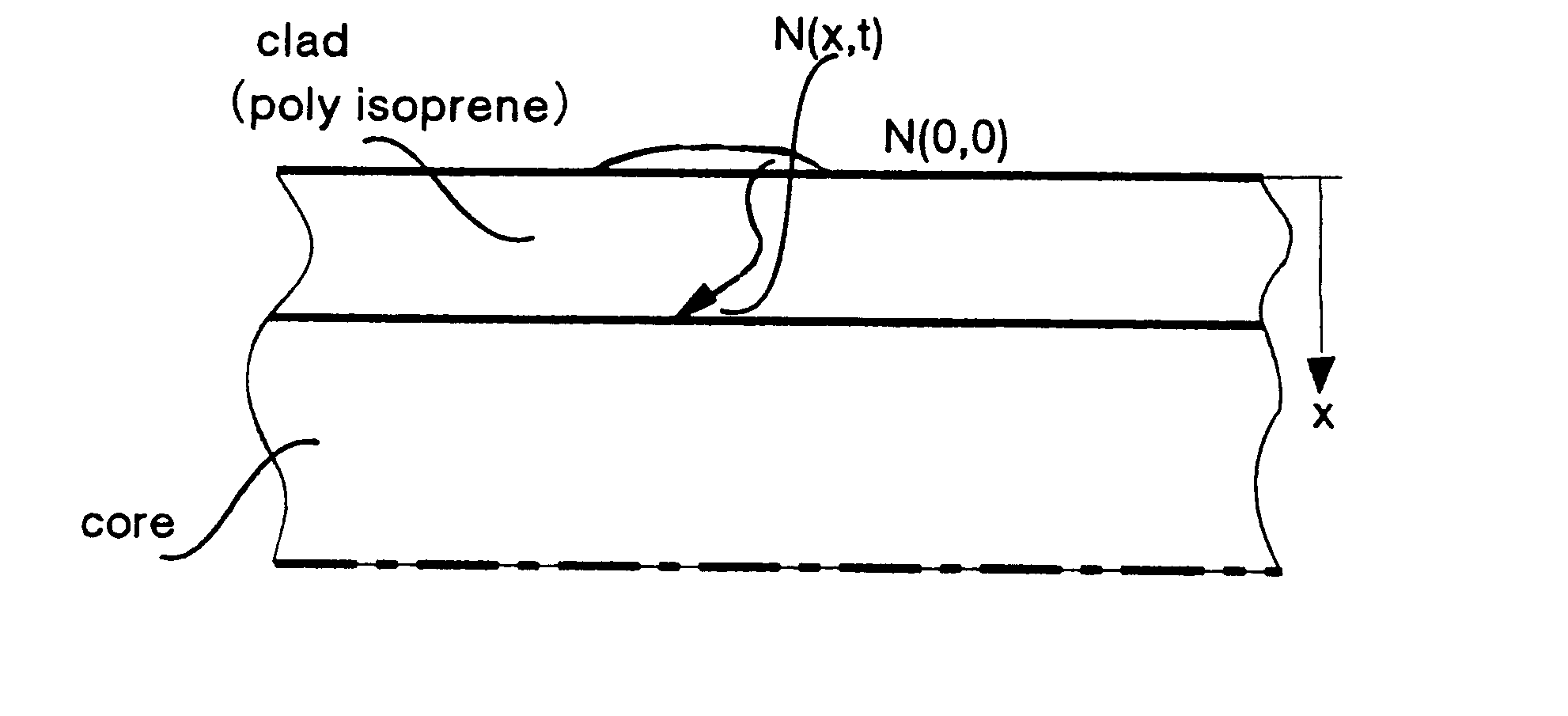
Plastic fiber core made of Atone (made by Fujitsukasei) with an index of refraction of 1.51 was used as the core material. Polyisoprene with molecular weight of 410,000 and index of refraction of 1.52 was used as the clad material.

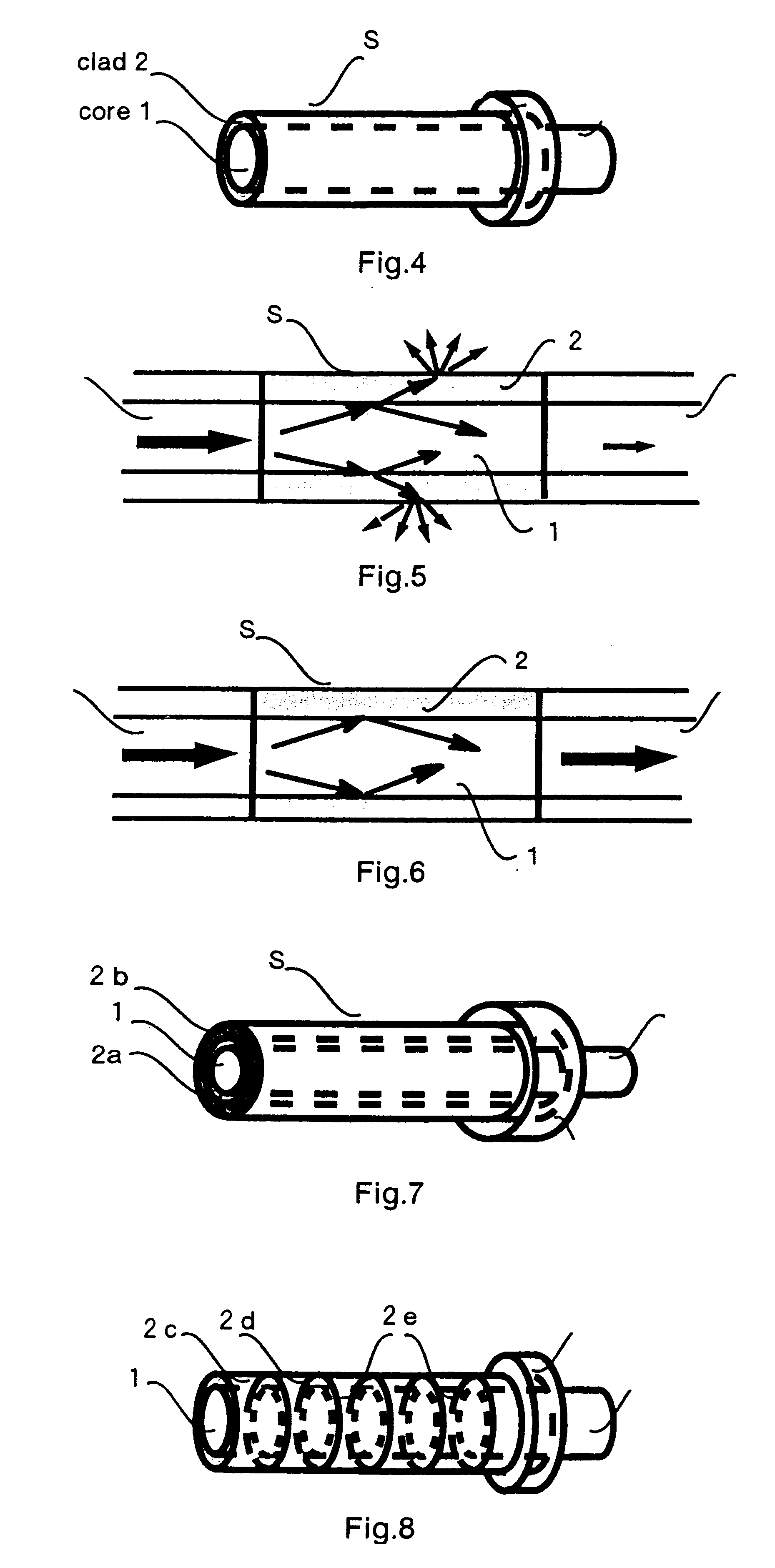
A film of thicknesses of 4 .mu.m, 6 .mu.m and 8 .mu.m was spin coated from the isoprene solution. These films were attached to the Atone core with diameter of 1 mm and length of 20 mm. FIG. 4 shows the core 1 and clad 2 and the resulting sensor S.

The sensor S was made into sensor device shown in FIG. 9. Hexane was measured using this system, and the result is shown in FIGS. 16 to 18.

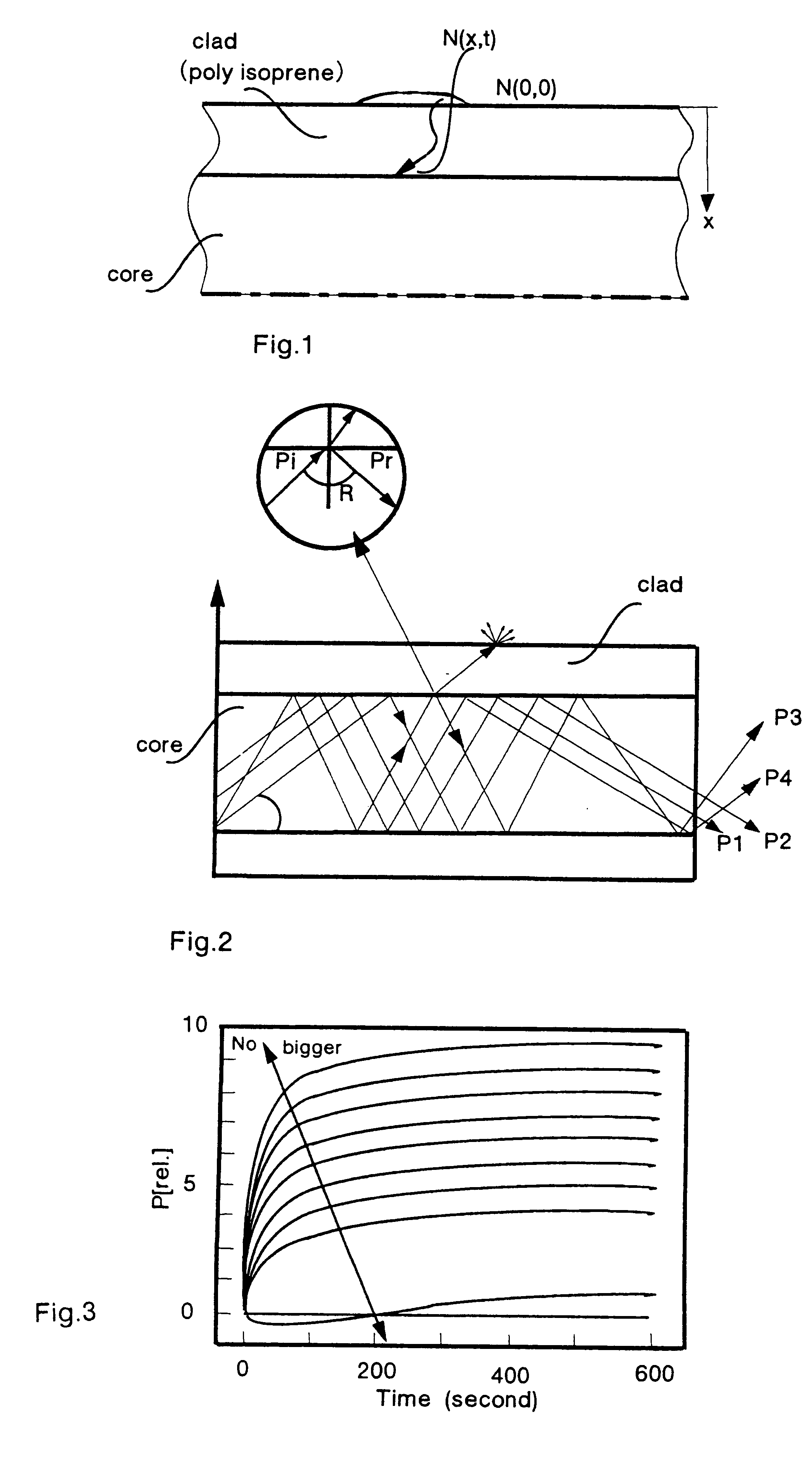
When the sensor S is exposed to hexane, the index of refraction of clad 2 will begin to decrease. The index of refraction changes of n.sub.co.ltoreq.n.sub.cl to n.sub.co

example 2

Method to Measure H.sub.2 O

A solution of 10% polyvinyl alcohol (PVA) in water is coated on the surface of the plastic fiber core Atone (made by Fujitsukasei). Atone with an index of refraction of 1.51 is used as the corel material. After the water evaporates, PVA is cross linked by immersing the coated core into a solution of 1 M hydrochloric acid with 5% aqueous glutaraldehyde for 10 min. at 30.degree. C. The coated PVA is 5 km, and becomes clad 2. The sensor S like one shown in FIG. 4 is formed. The sensor is used to form a sensor device as shown in FIG. 9. The result of using this system to measure H.sub.2 O is shown in FIG. 19.

When the sensor is placed in the H.sub.2 O environment, then the index of refraction of clad 2 decreases, and changes from n.sub.co.ltoreq.n.sub.cl to n.sub.co >n.sub.cl. The sensor changes from light leakage mode to wave guide mode, and consequently, the light output intensity of light emitter like photodetector (6) increases making the detection of H.sub...

example 3

Method to Measure Diethylether

Novolak resin, the clad material, was fabricated as follows: 50 g of purified phenol, 37 ml of 37% formaldehyde aqueous solution, and 0.03 ml of aqueous solution of HCI (35%) for catalyst was added to a 500 ml four-necked flask. The flask is heated in an oil bath while the mixture is stirred. The mixture is refluxed for an additional 2 hours at 90.degree. C. The reacted material is then transferred to an evaporation dish and precipitated in ice water.

This novolak polymer is coated around the corel material made from Atone to form a 5 .mu.m clad 2 material. A sensor similar to that shown in FIG. 4 is formed. The sensor S was made into sensor device shown in FIG. 9. Diethylether was measured using this system, and the result is shown in FIG. 20.

When the sensor is placed in the diethylether environment, then the index of refraction of clad 2 decreases, and changes from n.sub.co.ltoreq.n.sub.cl to n.sub.co


PUM


Abstract

The optical sensor of the present invention detects both the existence and concentration of substances by changing from light leakage mode to wave guide mode when the sensor is exposed to the substances to be detected. The changes in the mode results in a large change in optical output. This change is measured and the substance is identified and/or measured with high sensitivity.The change in light leakage mode to wave guide mode of the sensor is possible by having a clad material around the core material, with the clad material decreasing in the index of refraction when exposed to the substance to be detected. When the index of refraction of the clad becomes less than that of the core material, the sensor changes from the light leakage mode and operates in the wave guide mode. Changes in light intensity output from the sensor is measured over time, and correlated to the substance to be detected.

Description

The present invention relates to the field of optical sensors.The use of sensors to detect chemical substances both qualitatively as well as quantitatively is a growing field. Sensor use is not limited to industrial sectors. Sensors are used in air pollution studies, medical hygiene and numerous other fields.Many of the existing sensors are electrically driven, and thus have safety problems. For example, many of the submersion sensors are electrical devices and thus have the possibility of current leakage when immersed in water. Other electrically driven sensors, such as alarm sensors that use metallic conductors, cannot be used due to the existence of an electromagnetic field.Optical fibers have been typically used to transmit light. The theory of the optical transmission in optical fibers is complex. Generally, however, as light enters the end of a long optical fiber, some of the light will travel in a straight axial path thorough the center of the fiber, while the remaining light...

Claims


Application Information

Patent Timeline
IPC IPC(8): G01N21/77G02B6/02G02B6/036G01N21/41
CPCG01N21/7703G02B6/02033
Inventor MUTO, SHINZOMORISAWA, MASAYUKIMACHIDA, HIDEAKILIANG, CHUANXINNAOTO, NODA
Owner MUTO SHINZO
Why Eureka
Try Eureka