Film, Manufacturing Method Thereof, Polarization Plate Using the Film, and Liquid Crystal, and Display Device Using the Polarizing Plate

Inactive Publication Date: 2008-06-12
FUJIFILM CORP
View PDF5 Cites 41 Cited by
  • Summary
  • Abstract
  • Description
  • Claims
  • Application Information

AI Technical Summary

Benefits of technology

[0006]In summary, it has not yet been present at present an anti-glare film or an anti-reflection film capable of satisfying prevention of the degradation of the anti-glare p

Problems solved by technology

On the other hand, while an anti-glare film having a high internal scattering property used generally as means for improving the dazzling described above is used also to such application, since high internal scattering property brings about a problem of lowering the contrast in the dark room, this is not always optimal to such application.
Further, the display device is often used in a bright room for such application and when a film having the existent anti-glare layer is applied to the surface of the display device, this has resulte

Method used


Image

  • Film, Manufacturing Method Thereof, Polarization Plate Using the Film, and Liquid Crystal, and Display Device Using the Polarizing Plate
  • Film, Manufacturing Method Thereof, Polarization Plate Using the Film, and Liquid Crystal, and Display Device Using the Polarizing Plate
  • Film, Manufacturing Method Thereof, Polarization Plate Using the Film, and Liquid Crystal, and Display Device Using the Polarizing Plate

Examples


example 1

(1) Coating of Anti-Glare Layer

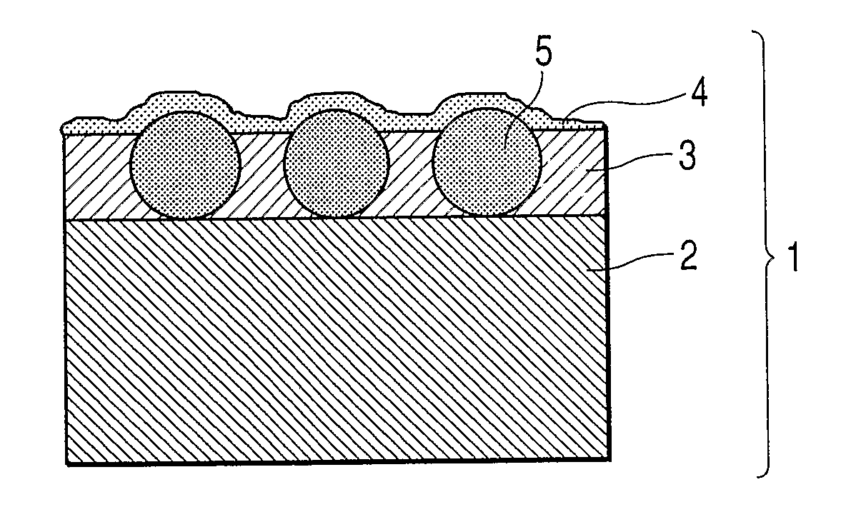
[0326]A triacetyl cellulose film of 80 μm thickness (TAC-TD80U, manufactured by Fuji Photofilm Inc.) was unwound from a roll form as a transparent support, the coating solution A for use in the anti-glare layer was coated by a die coat method with the device constitution and the coating conditions described below and, after drying at 30° C. for 15 sec and 90° C. for 20 sec, UV-rays at an irradiation dose of 90 mJ / cm2 were irradiated under nitrogen purge by using an air-cooled metal halide lamp (manufactured by I Graphics Co.) at 160 W / cm to cure the coating layer and an anti-glare layer of 6 μm thickness having an anti-glare property was formed and wound up.

Basic Condition:

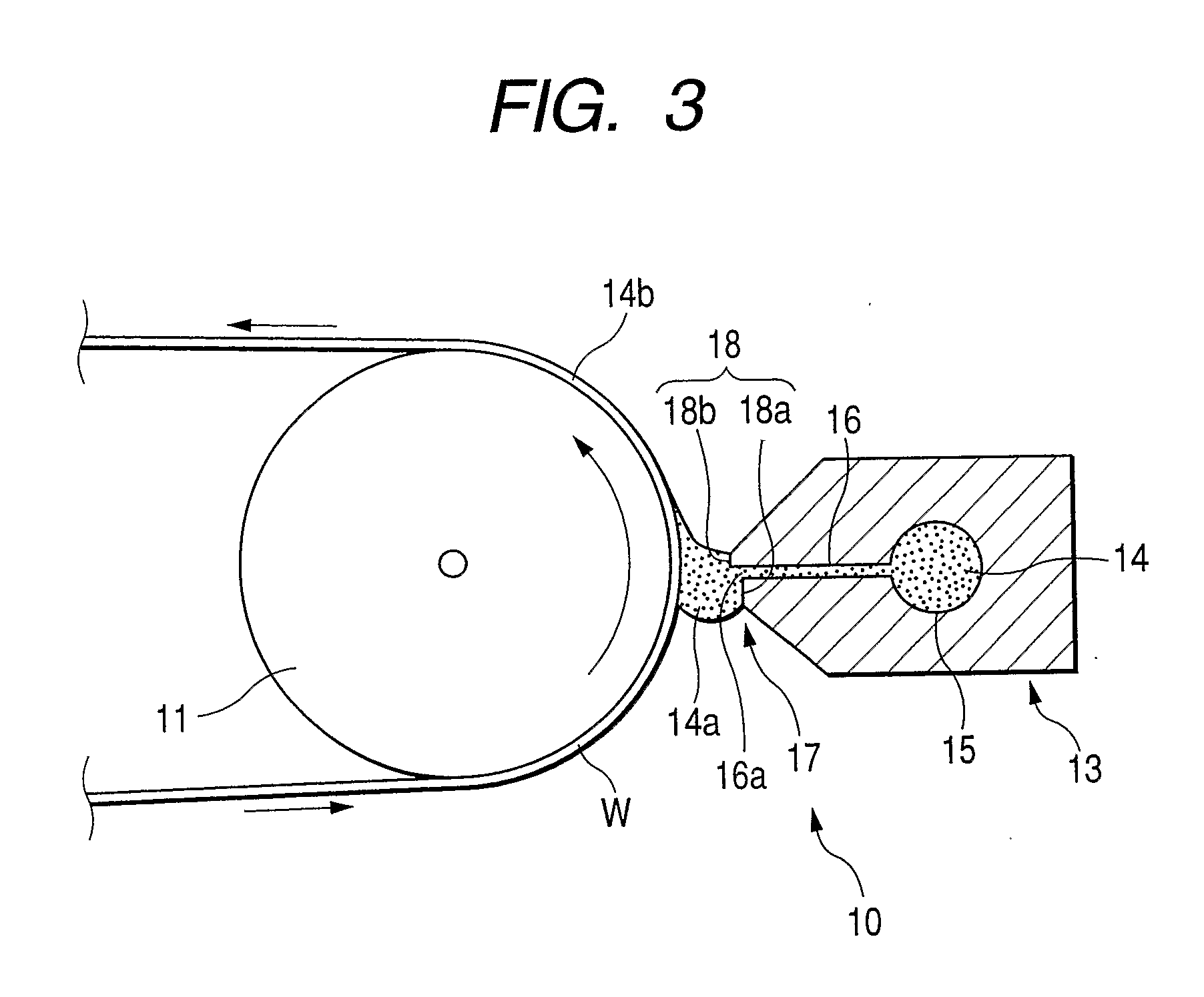
[0327]A slot die 13 having an upper stream lip land length lup of 0.5 mm, a down stream lip land length ILO of 50 μm, the opening length of the slot 16 in the web running direction of 150 μm and a length of the slot 16 of 50 mm was used. The gap between the upstream lip land 18a and ...

example 2

Preparation of Polarizing Plate)

[0361]A polarizing plate was manufactured by bonding for protection a triacetyl cellulose film (TAC-TD80U, manufactured by Fuji Photofilm Co., hereinafter referred to as TAC film) of 80 μm thickness which was dipped in an aqueous 1.5 mol / L of NaOH solution at 55° C. for 2 min and then neutralized and washed with water, and each of anti-glare and anti-reflection films prepared in Example 1 (after saponification treatment: Example 1-1 to Example 1-10, Comparative Example 1-3) on both surfaces of a polarization film prepared from polyvinyl alcohol by adsorption of iodine and stretching. The surface of the transparent support of the anti-glare anti-reflection film prepared in Example 1 was bonded to the polarization film. They are Example 2-1 to Example 2-10 and Comparative Example 2-1 to Comparative Example 2-3, respectively.

[0362]Further, a polarizing plate was manufactured by using the triacetyl cellulose film after the saponification treatment for the...

example 3

Evaluation for Polarizing Plate

[0363]Display devices were manufactured by peeling a portion of a polarizing plate in each of liquid crystal television sets on the viewing surface and replacing the portion with polarizing plates of Example 2-1 to Example 2-10, Comparative Example 2-1 to Comparative Example 2-4, and Comparative Example 2-2 manufactured in Example 2 by the combination as shown in the following Table 2. Evaluation of the following items was conducted for the obtained display devices. The result is shown in Table 2.

(1) White Blurring

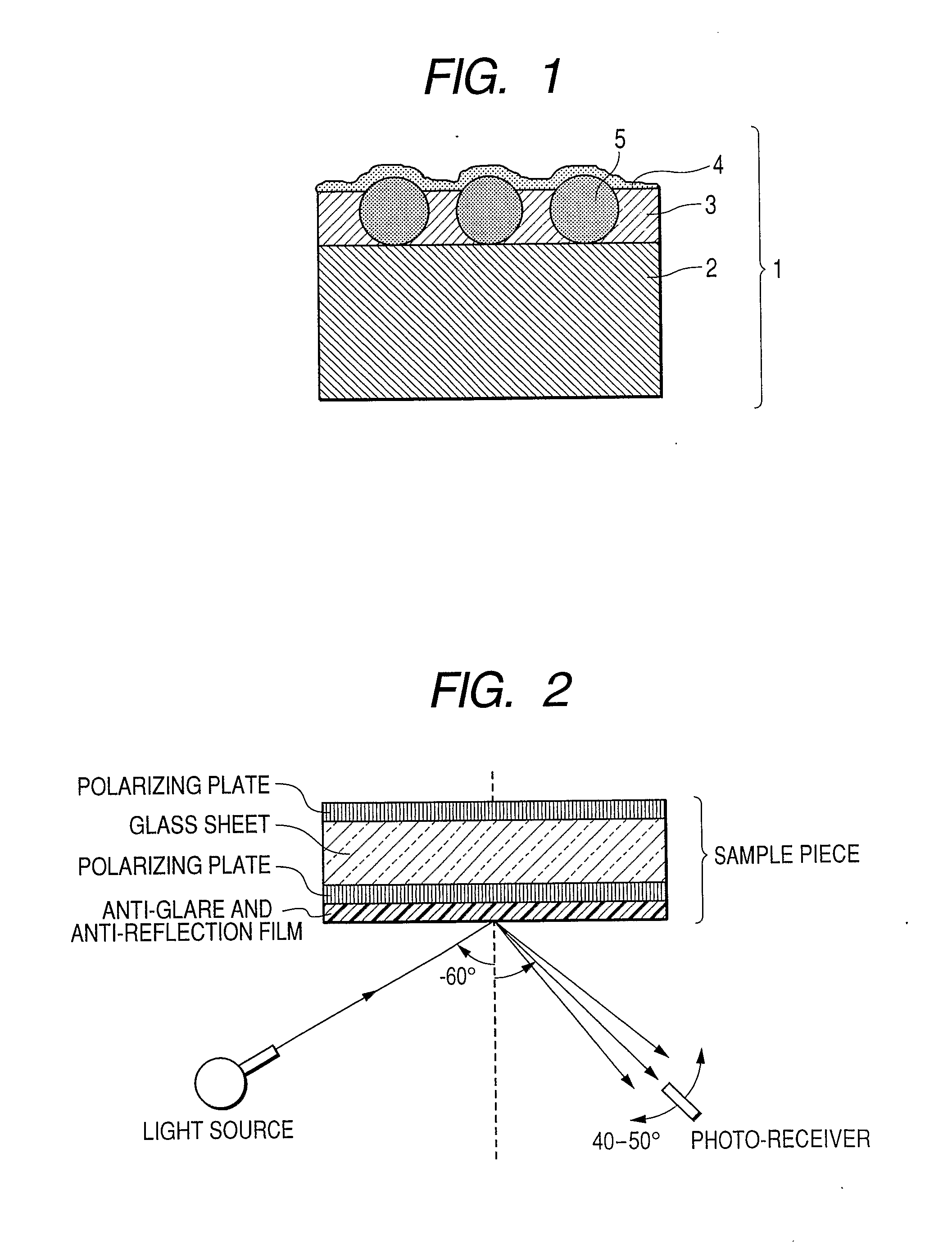
[0364]For LCD television panels having fineness and image size described in the table (each of VA mode), the polarizing plates on the side of the surface were replaced with polarizing plates using two sheets of TAC films having smooth surface as the protective film, and a fluorescence lamp (8000 cd / m2) with no louver was reflected from an angle of 60° above onto the panel in the state of whole black display. A white lightening state (white bl...


PUM

PropertyMeasurementUnit
Fractionaaaaaaaaaa
Percent by massaaaaaaaaaa
Angleaaaaaaaaaa

Abstract

A film comprises: a transparent support; and an anti-glare layer having a haze value due to internal scattering of from 0 to 40% and a haze value due to surface scattering of from 0.3 to 20%.

Description

TECHNICAL FIELD[0001]The present invention concerns an anti-glare film, an anti-reflection film, a manufacturing method thereof, a polarizing plate and an image display device and, more specifically, it relates to an anti-glare film having an anti-glare layer with a predetermined internal scattering property and a predetermined surface scattering property, an anti-reflection film having the anti-glare layer and a low refractive index layer, a manufacturing method thereof, a polarizing plate using the anti-reflection film as a surface protective film, and an image display device using the anti-glare film, the anti-reflection film or the polarizing plate.BACKGROUND ART[0002]The anti-glare film has normally a surface scattering property and is disposed to the extreme surface of a display for preventing transfer of images due to reflection of external light in display devices such as CRT, plasma display (PDP), electroluminescent display (ELD), field emission display (FED), surface-condu...

Claims


Application Information

Patent Timeline
IPC IPC(8): G02B1/11B05D5/06G02B5/30
CPCG02B1/111C08F222/1006C08F222/102B05D1/26G02B5/30G02F1/1335
Inventor NAKAMURA, KAZUHIROINOUE, KATSUMIMURAMATSU, YUUZOUINOUE, RIKIO
Owner FUJIFILM CORP
Why Eureka
Try Eureka