Rare earth-doped core optical fiber

a technology of optical fiber and core, which is applied in the direction of cladded optical fiber, instruments, optical elements, etc., can solve the problems of affecting the life affecting the performance of the optical fiber, so as to achieve the effect of reducing the refractive index, and sufficient output power of the laser oscillation

Inactive Publication Date: 2010-03-18
THE FUJIKURA CABLE WORKS LTD
View PDF4 Cites 43 Cited by
  • Summary
  • Abstract
  • Description
  • Claims
  • Application Information

AI Technical Summary

Benefits of technology

[0035]A rare earth-doped core optical fiber of the present invention includes a core formed of a silica glass including at least aluminum and ytterbium, a clad provided around the core and formed of a silica glass having a lower refractive index than that of the core, and a polymer layer provided on the outer circumference of the clad and having a lower refractive index than that of the clad. Aluminum and ytterbium are doped to the core such that a photodarkening loss increase amount TPD satisfies inequality (A). As a result if the rare earth-doped core optical fiber of the present invention is used as an optical fiber laser using a rare earth element as a laser active medium, since the output of light having a laser oscillation wavelength is not attenuated even when laser oscillation is performed for a long time, it is possible to manufacture an optical fiber laser capable of maintaining a sufficient output power of laser oscillation even when used for a long period of time.

Problems solved by technology

If a rare earth element of about 0.1% by mass or more is doped in a SiO2 glass or a GEO2—SiO2-based glass used in a general optical fiber, there is a disadvantage that so-called concentration quenching occurs.
This is a phenomenon in which the energy of electrons excited by agglomerating (clustering) rare earth ions in the glass is apt to be lost in a non-radioactive process, and light emission characteristics such as the life time or efficiency of light emission is damaged.

Method used


Image

  • Rare earth-doped core optical fiber
  • Rare earth-doped core optical fiber
  • Rare earth-doped core optical fiber

Examples


first example of first embodiment

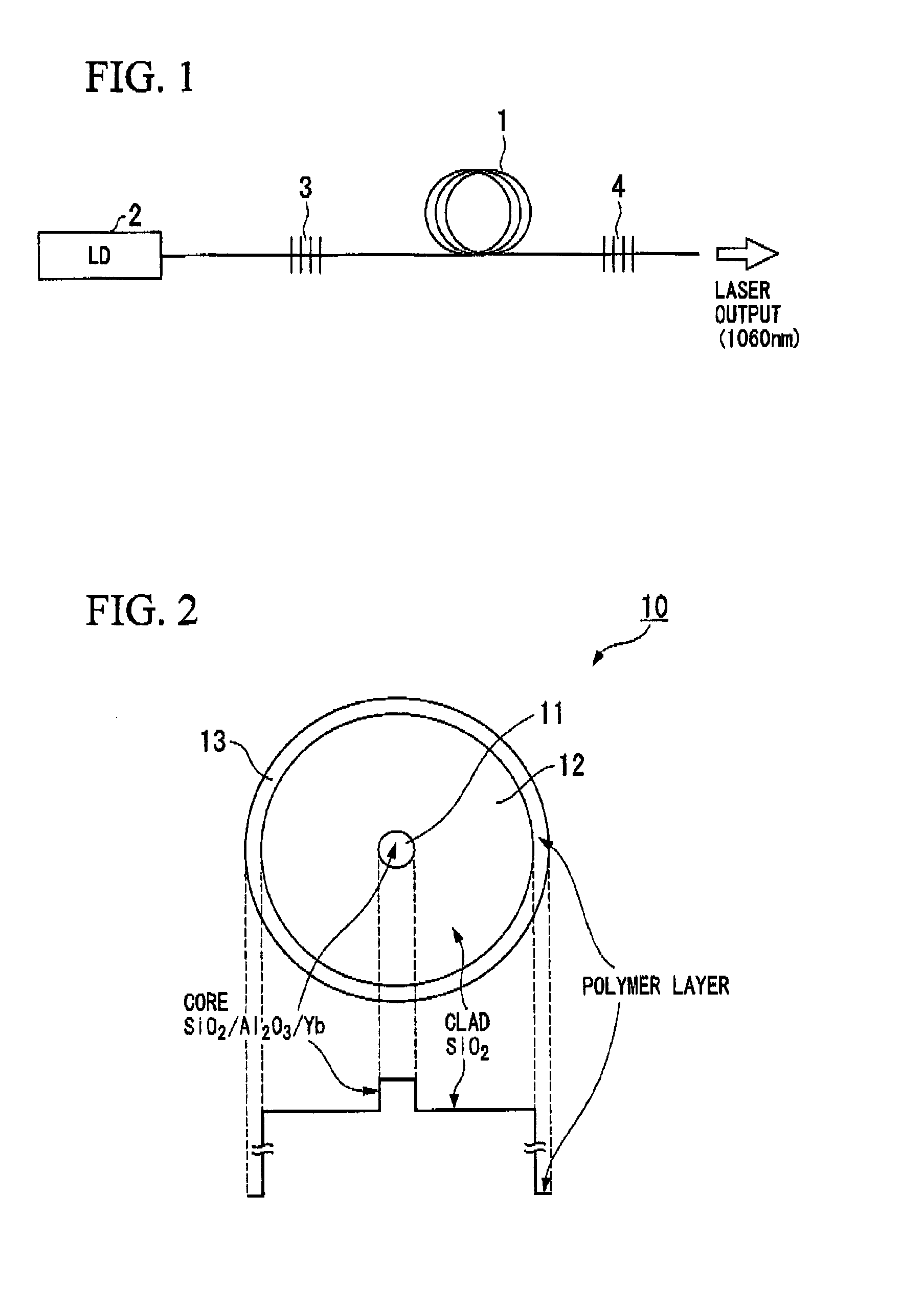
[0079]A first example of a first embodiment of a rare earth-doped core optical fiber according to the present invention will be described with reference to FIG. 2.

[0080]The rare earth-doped core optical fiber 10 of the present example includes a core 11 to which a rare earth element is doped, a clad 12 surrounding the core 11 and having a refractive index lower than that of the core 11, and a polymer layer 13 provided on the outer circumference of the clad 12 and having a refractive index lower than that of the clad 12.

[0081]The rare earth-doped core optical fiber 10 of FIG. 2 includes the core 11 formed of a silica glass including aluminum (Al) and ytterbium (Yb) which is a rare earth element, the clad 12 formed of a silica (SiO2) glass provided around the core 11, and the polymer layer 13 provided on the outer circumference of the clad 12 and having the refractive index lower than that of the clad 12. Furthermore, the core has an Al concentration of 2% by mass or more. In addition...

second example of first embodiment

[0087]A second example of the first embodiment of a rare earth-doped core optical fiber according to the present invention will be described using a detailed example.

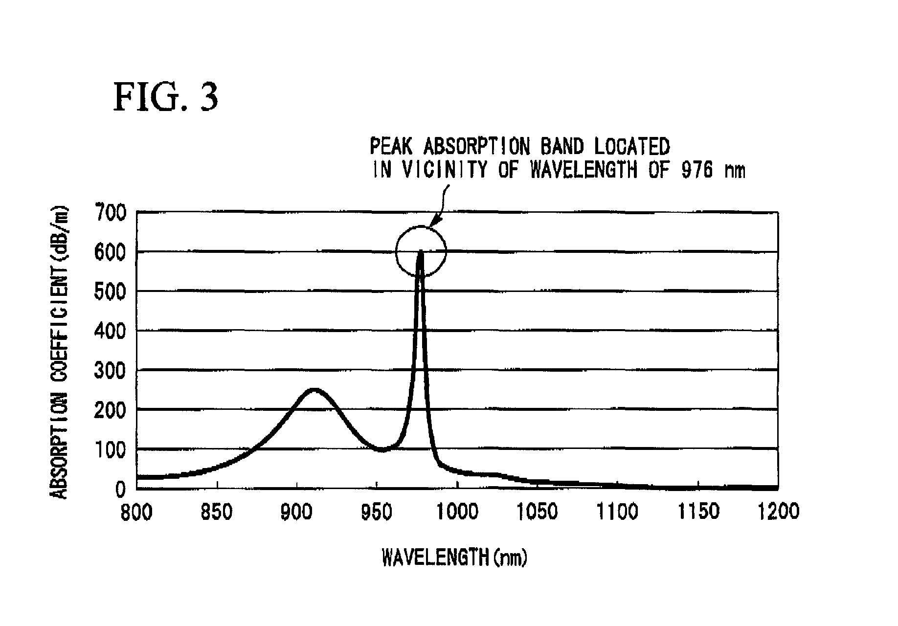
[0088]The rare earth-doped core optical fiber of the present example has substantially the same basic structure as that of the rare earth-doped core optical fiber shown in FIG. 2, but it is a rare earth-doped core optical fiber which has the core comprising a silica glass containing aluminum (Al) and ytterbium (Yb) as a rare earth element, in which aluminum and ytterbium are doped so as to satisfy the inequality (A), taking a concentration of aluminum contained in the core as DAl (unit: % by mass), and a peak absorption coefficient of the absorption band which appears around a wavelength of 976 nm in the absorption band by ytterbium contained in the core as AYb (unit: dB / m).

[0089]In the inequality (A), TPD is an allowable loss increase by photodarkening at a wavelength of 810 nm in the Yb-doped core optical fiber, expre...

second embodiment

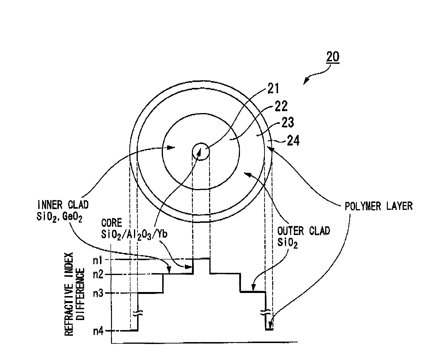
[0099]A second embodiment of a rare earth-doped core optical fiber according to the present invention will be described with reference to FIG. 4.

[0100]The rare earth-doped core optical fiber 20 of the present example includes a core 21 to which a rare earth element is doped, an inner clad 22 located in the neighborhood of the core 21, an outer clad 23 located outside the inner clad 22, and a polymer layer 24 located outside the outer clad 23.

[0101]The rare earth-doped core optical fiber 20 of FIG. 4 includes the core 21 formed of a silica glass including aluminum (Al) and ytterbium (Yb) which is a rare earth element, the inner clad 22 provided in the neighborhood of the core 21 and formed of a silica glass including germanium (Ge), the outer clad 23 provided outside the inner clad 22 and formed of a silica glass, and the polymer layer 24 provided outside the outer clad 23 and having a refractive index lower than that of the outer clad 23.

[0102]This rare earth-doped core optical fibe...


PUM

PropertyMeasurementUnit
oscillation wavelengthaaaaaaaaaa
refraction indexaaaaaaaaaa
refractive indexaaaaaaaaaa

Abstract

A rare earth-doped core optical fiber includes a core comprising a silica glass containing at least aluminum and ytterbium, a clad provided around the core and comprising a silica glass having a lower refraction index than that of the core, and a polymer layer provided on the outer circumference of the clad and having a lower refractive index than that of the clad, wherein aluminum and ytterbium are doped into the core such that a loss increase by photodarkening, TPD, satisfies the following inequality (A). By this rare earth-doped core optical fiber, it is possible to manufacture an optical fiber laser capable of maintaining a sufficient laser oscillation output even when used for a long period of time.TPD≧10{−0.655*(D<sub2>Al< / sub2>)−4.304*exp{−0.00343*(A<sub2>Yb< / sub2>)}+1.274}  (A)

Description

TECHNICAL FIELD[0001]The present invention relates to a rare earth-doped core optical fiber and, more particularly, a rare earth-doped core optical fiber which is used as an optical amplification fiber such as an optical fiber laser or an optical amplifier and is particularly suitable for the configuration of the optical fiber laser.[0002]This application is a continuation application based on a PCT Patent Application No. PCT / JP2008 / 057734, filed Apr. 22, 2008, whose priority is claimed on Japanese Patent Application No. 2007-115492 filed Apr. 25, 2007, the entire content of which are hereby incorporated by reference.BACKGROUND ART[0003]Recently, it has been reported that a single-mode optical fiber laser or optical amplifier, which employs an optical fiber doped with a rare earth element such as neodymium (Nd), erbium (Er), praseodymium (Pr), and ytterbium (Yb), as a laser active medium (hereinafter referred to as a rare earth doped optical fiber) has many possible applications in ...

Claims


Application Information

Patent Timeline
Patent Type & Authority Applications(United States)
IPC IPC(8): G02B6/02G02B6/00
CPCG02B6/02033G02B6/03633G02B6/03688H01S3/06716H01S3/06729H01S3/176H01S3/0675H01S3/094007H01S3/1618H01S3/1693H01S3/06741
Inventor IKEDA, MASASHIYAMADA, NARITOSHIHIMENO, KUNIHARUNAKAI, MICHIHIROKITABAYASHI, TOMOHARU
Owner THE FUJIKURA CABLE WORKS LTD
Why Eureka
Try Eureka