
Remote controlled LED based id emitter

a remote control and led emitter technology, applied in the field of internet of things, can solve problems such as the reduction of receivable bandwidth of camera-based applications, and achieve the effects of reducing software complexity, increasing the accuracy of id estimation, and reducing receivable bandwidth

Inactive Publication Date: 2017-11-23
BASIC6
View PDF2 Cites 3 Cited by
  • Summary
  • Abstract
  • Description
  • Claims
  • Application Information

AI Technical Summary

Benefits of technology

The patent text describes a method to improve the accuracy and efficiency of identifying LED lights in camera-based applications. This is achieved by assigning unique IDs to each LED light and transmitting this data embedded in the VLC ID. The method allows for the ID to be set at manufacturing time or modified at a later time, and can also be used to change the ID to reflect the needs of each deployment. This method reduces software complexity, increases accuracy, and makes it easier to map the floor under networked lights. Additionally, the patent text describes the use of remote control and a mobile application to manage and control the LED lights. The method also includes a mechanism for generating authentication data to verify the identity of the LED light. The technical effects of this patent text include improved accuracy and efficiency in identifying LED lights, flexibility in setting and modifying IDs, and improved communication and control of LED lights.

Problems solved by technology

The issue of reduced receivable bandwidth by camera-based applications calls for transmission of as limited an amount of data as possible embedded in the VLC ID.

Method used


Image

  • Remote controlled LED based id emitter
  • Remote controlled LED based id emitter
  • Remote controlled LED based id emitter

Examples


Embodiment Construction

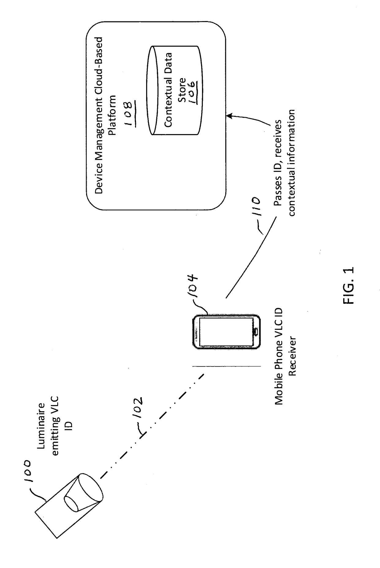
[0055]In FIG. 1, an embodiment a luminaire 100 repeatedly emits a signal transported over light 102, while a receiver 104 (such as, for example, a receiving mobile phone) interprets the signal carried by light 102, which may be visible light. The VLC ID of luminaire 100 so discerned may be passed to a networked data store 106, in a device management cloud based platform 108, via a network connection 110, in order to retrieve contextual information associated with the luminaire's ID, such as the location of the luminaire, from which may be inferred the approximate location of the receiver 104.

[0056]It possible to utilize non-visible spectra (infrared or ultraviolet) for transmitting the VLC ID and other information. Similarly, it is not strictly necessary for the emission of light to be carried out from a light fixture; it could be any container of circuitry and a light-emitting diode. The receiver 104 need not be in the form of a mobile phone, but could be any light-sensitive device...


PUM


Abstract

An apparatus includes a luminaire; power input for the luminaire; a modulation circuit for modulating the power input so that light output includes an identifier of the luminaire; and a programmable memory for storing at least one of the identifier of the luminaire and a modulation scheme for modulation of the luminaire to place a signal on the light. A method for modulating light includes storing in programmable memory an identifier for the luminaire, the identifier being used to modulate the light, and / or a modulation scheme for modulation of the luminaire; and changing content of programmable memory to change the identifier and / or the modulation scheme. A method of efficiently deploying the luminaires and identifying their locations to a network is disclosed. A method of multi-factor authentication using authentication data transmitted by modulating the light emitted by a luminaire is also disclosed.

Description

[0001]This application claims priority from and the benefit of provisional application Ser. No. 62 / 338,815 filed on May 19, 2016, which is incorporated herein by reference, in its entirety, for all purposes.BACKGROUND OF THE DISCLOSURE1. Field of the Disclosure[0002]The present disclosure relates to the Internet of Things (IoT). The IoT is essentially the set of connectable and identifiable electronic devices that are being installed in our surroundings at an increasing rate. This disclosure also relates to the technology of light-emitting diodes (LED), semi-conductor based lighting, that has many advantages over incandescent light sources including lower energy consumption, longer lifetime, improved physical robustness, smaller size, and faster switching.2. Description of the Related Art[0003]This application is related to patent application Ser. No. 14 / 671,694 filed on Mar. 27, 2015, published as United States Patent Publication No. 2015 / 0281337, which claims priority from and the...

Claims


Application Information

Patent Timeline
Patent Type & Authority Applications(United States)
IPC IPC(8): H04L29/08H01L27/32G06F9/46G06F9/22
CPCH04L29/08099G06F9/467G06F9/223H01L27/32G08C2201/42G08C2201/93H04L67/10G06F9/226G08C17/02H04L67/025H04B10/116H04L67/125H04L2463/082H04W12/06H04W12/02H04W12/03H10K59/00G06F7/588H04L63/061H04L63/083H04W8/245H04W64/00
Inventor WENNEMYR, MAGNUSSAMSON, EDWARD
Owner BASIC6
Learn More