
Cutting apparatus

Inactive Publication Date: 2017-11-30
DISCO CORP
View PDF26 Cites 0 Cited by
  • Summary
  • Abstract
  • Description
  • Claims
  • Application Information

AI Technical Summary

Benefits of technology

The present invention is about a cutting apparatus that reduces contamination when cutting in a dry state and makes maintenance easier. The apparatus has a blade that collects cut dust from the workpiece and rotates within a covers. The cut dusts are then discharged out through a tubular member under suction, minimizing the chance of scattering and reducing contamination on the workpiece and other parts of the apparatus. The technical effect of this invention is minimized contamination and easier maintenance of the cutting apparatus.

Problems solved by technology

However, when a dry workpiece is cut by a cutting blade, cut dusts tend to scatter backwards as contaminants due to the rotation of the cutting blade and spread into a wide area.
The contaminants are likely to be deposited on the upper surface of the workpiece being cut, contaminating the workpiece, and to be applied to various parts of the cutting apparatus, making it hard for the operator to perform its maintenance task.

Method used


Image

  • Cutting apparatus
  • Cutting apparatus
  • Cutting apparatus

Examples


Embodiment Construction

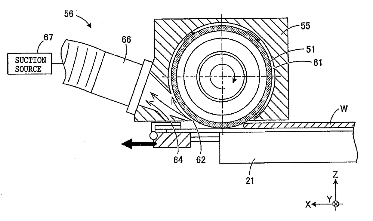
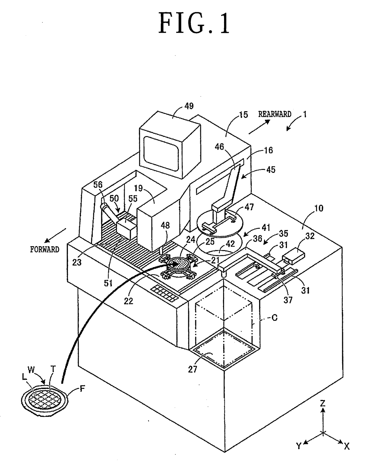
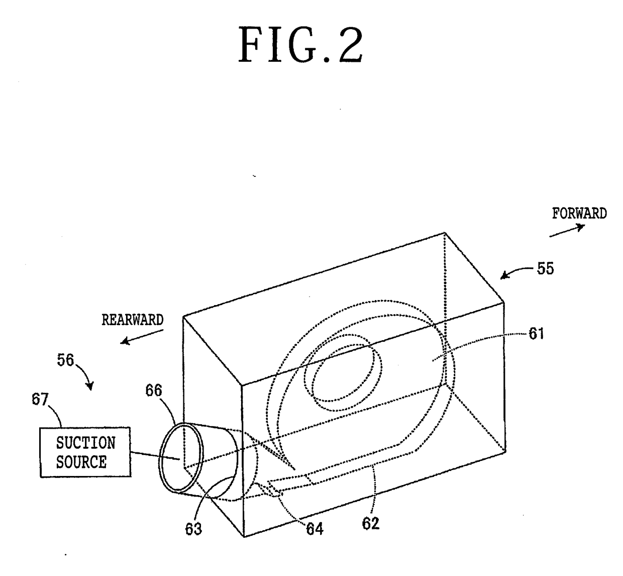
[0016]A cutting apparatus according to an embodiment of the present invention will be described below with reference to the accompanying drawings. FIG. 1 depicts in perspective the cutting apparatus, denoted by 1, according to the present embodiment. The principles of the present invention are not limited to the cutting apparatus 1 depicted in FIG. 1, but are also applicable to other cutting apparatus insofar as they are provided with a blade cover according to the present embodiment.

[0017]As depicted in FIG. 1, the cutting apparatus 1 is arranged to cut, in a dry state, a plate-shaped workpiece W held on a chuck table 21 with a cutting blade 51 and to retrieve cut dusts produced from the workpiece W when it is cut by the cutting blade 51. The workpiece W has its upper surface demarcated into a plurality of areas by a grid of projected dicing lines L. The workpiece W is loaded into the cutting apparatus 1 while being supported on a ring frame F by a dicing tape T. The workpiece W sh...


PUM


Abstract

A cutting apparatus includes a chuck table for holding a workpiece, a cutting blade for cutting the workpiece which is held by the chuck table, and a blade cover disposed in covering relation to an outer circumference of the cutting blade. The workpiece is cut in a dry state by the cutting blade while cut dusts produced from the workpiece and rotating with the cutting blade are being discharged through a tubular member under suction by a cut dusts retrieving unit mounted on the blade cover.

Description

BACKGROUND OF THE INVENTIONField of the Invention[0001]The present invention relates to a cutting apparatus that is provided with a blade cover for a cutting blade.Description of the Related Art[0002]Workpieces including semiconductor wafers with devices such as integrated circuits (ICs) formed on their surfaces and packaged substrates with a plurality of device dusts sealed thereon by resin layers are cut into individual dusts by the annular cutting blade of a cutting apparatus. Normally, the annular cutting blade of the cutting apparatus has its outer circumference covered with a blade cover having nozzles for ejecting cutting water. While the cutting apparatus of this type is cutting a workpiece, the nozzles supply cutting water to the cutting blade and the workpiece to cool the frictional heat generated at the point where the workpiece is cut and also to clean the surface of the workpiece (see, for example, Japanese Patent Laid-Open No. 2015-145046).SUMMARY OF THE INVENTION[0003...

Claims


Application Information

Patent Timeline
IPC IPC(8): B26D7/18B26D7/01B26D5/00
CPCB26D7/1863B26D5/007B26D7/018H01L21/304H01L21/3043H01L21/78B26D1/14B26D7/22
Inventor INOUE, TAKAAKINOZAKI, MASAO
Owner DISCO CORP
Learn More