
Movable emission control system for auxiliary diesel engines

a technology of auxiliary diesel engines and emission control systems, which is applied in the direction of marine propulsion, vessel construction, separation processes, etc., can solve the problems of cumbersome and expensive current options for connecting to alternative power sources, and inability to meet the needs of additional demand, etc., to achieve efficient, economical and regulatory compliance, and reduce emissions. , the effect of minimal environmental impa

Active Publication Date: 2017-11-30
CLEAN AIR ENG MARITIME INC
View PDF8 Cites 15 Cited by
  • Summary
  • Abstract
  • Description
  • Claims
  • Application Information

AI Technical Summary

Benefits of technology

The patent describes a system that allows a ship to use its auxiliary diesel engine or engines with reduced emissions while at berth. This system helps comply with regulations and restrictions on emissions, and it provides a safe and efficient alternative to shore power for ocean-going ships that cannot or choose not to use shore power. The system is connected to the ship's auxiliary diesel engine and consists of two essential elements: an emissions capturing system and an emissions control system.

Problems solved by technology

Current options for connecting to alternative power sources are often cumbersome and expensive, and are sometimes not available for a number of reasons, including one or more of the following reasons: (i) ships are not wired for shore power; (ii) shipping companies do not want the expense of converting to shore power; (iii) terminals have no shore power available; or (iv) shore power is over-stressed and is unable to provide for additional demand.
Currently, few or no alternative control techniques are available that achieve equivalent emission reductions.
Absent such an economical solution, some vessels will be unable to dock at major ports (such as those in California), thus adversely affecting shippers' businesses.
In addition, ports subject to the CARB at-berth regulation and / or regulations, or other similar restrictions, will also be adversely affected: not only will they lose business from ships that do not or cannot comply with applicable restrictions or regulations, but also they will be hindered in expanding business by attracting ships to dock that are similarly non-compliant.

Method used


Image

  • Movable emission control system for auxiliary diesel engines
  • Movable emission control system for auxiliary diesel engines
  • Movable emission control system for auxiliary diesel engines

Examples


Embodiment Construction

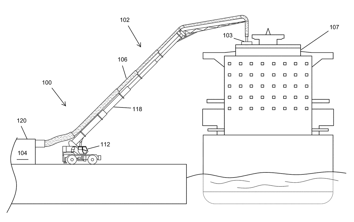
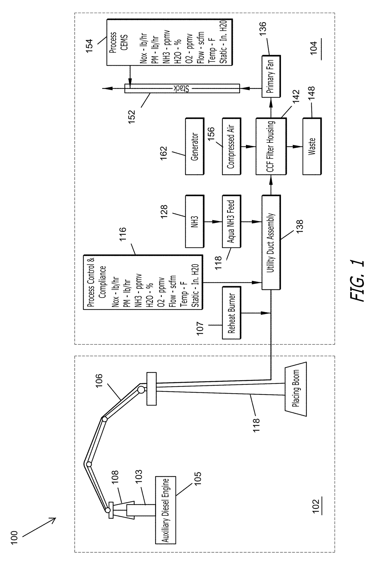
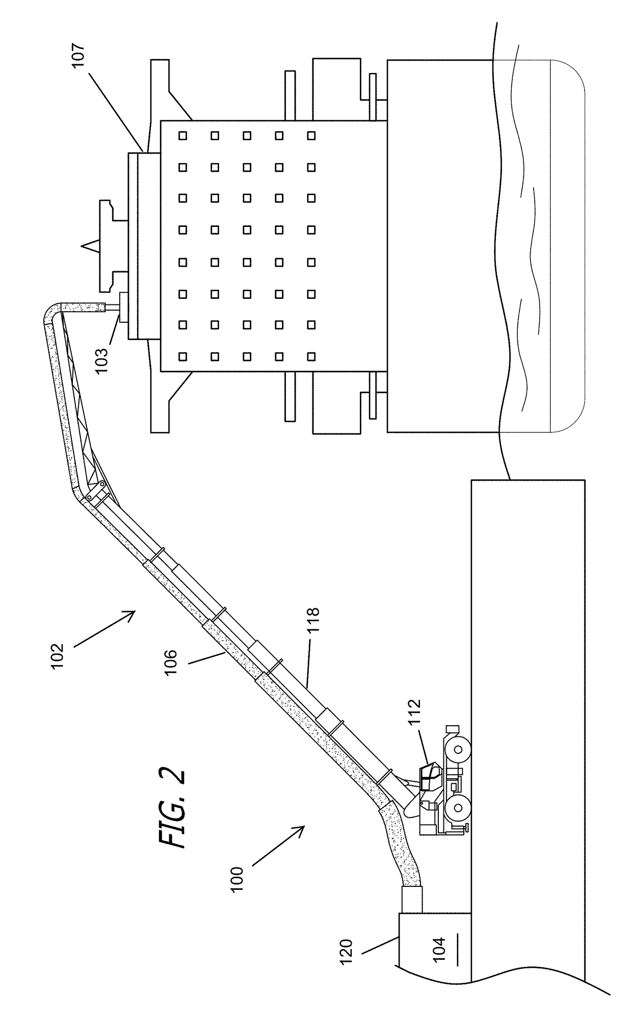
[0029]As illustrated by FIGS. 1-10, the present invention relates to an emissions reduction system 100 that is capable of reducing emissions from engines to allow for compliance with applicable regulations governing emissions, such as the requirements of the CARB regulation. As shown in FIGS. 1 and 2, the emissions reduction system 100 comprises both an emissions capturing system 102 and an emission control system 104.

[0030]As illustrated by FIG. 1, the emission capture system 102 extends a utility duct 106 over the ship's exhaust stack 103 to capture the exhaust from the auxiliary diesel engine 105. The duct 106 includes a connector and / or stack adapter 108 that connects the utility duck 106 to the exhaust. The duct 106 is extended over the ship's exhaust stack 103 using a crane or boom 118 that can be mobile or fixed. Those skilled in the art will recognize that any capturing system may be used that is capable of capturing a sufficient quantity of emissions so that the exhaust, on...


PUM

PropertyMeasurementUnit
temperatureaaaaaaaaaa
shore poweraaaaaaaaaa

Abstract

A mobile emissions control system is provided for diesel engines operated on ocean-going ships at-berth. The emissions control system comprises two essential elements: an emissions capturing system and an emissions control system. The emissions control system may be mounted on a towable chassis or mounted on a barge, allowing it to be placed alongside ocean-going ships at-berth. The emission capturing system captures exhaust from a ship's diesel engine and conducts it into the emissions control system, which cleans the exhaust and then passes clean air into the atmosphere through an exhaust outlet.

Description

RELATED APPLICATIONS[0001]This is a continuation-in-part application and claims priority of U.S. Application Ser. No. 62 / 401,753, filed on Sep. 29, 2016, titled MOVABLE EMISSION CONTROL SYSTEM FOR AUXILIARY DIESEL ENGINES; and U.S. patent application Ser. No. 15 / 231,071, filed on Aug. 8, 2016, titled EMISSION CONTROL SYSTEM FOR AUXILIARY DIESEL ENGINES; both application of which are incorporated in their entirety by reference in this application.FIELD OF THE INVENTION[0002]The invention relates to a movable emissions reduction system, and in particular, a movable airborne toxic emissions reduction system for auxiliary diesel engines operated on ocean-going ships (or vessels) at-berth.BACKGROUND OF THE INVENTION[0003]The California Air Resources Board (“CARB”) has adopted a regulation commonly called the at-berth regulation, the purpose of which is to reduce emissions from diesel auxiliary engines on container ships, passenger ships and refrigerated-cargo ships while berthing at a Ca...

Claims


Application Information

Patent Timeline
Patent Type & Authority Applications(United States)
IPC IPC(8): F01N3/10B01D53/92F01N3/035B63H20/24B01D53/62B01D53/84C12M1/00
CPCF01N3/10F01N3/035B63H20/245C12M43/04B01D2257/504B01D53/92B01D53/62F01N2590/02B01D2258/012B01D53/84F01N13/004F01N3/021F01N2340/00F01N2610/02Y02T10/12
Inventor TONSICH, NICHOLAS G.
Owner CLEAN AIR ENG MARITIME INC
Learn More