Unlock instant, AI-driven research and patent intelligence for your innovation.

Foldable coil array

a coil array and array technology, applied in the field of non-invasive diagnostic imaging, can solve the problems of complex trade-off, degraded signal to noise ratio (snr) of the array, and inability to make too large rf coil arrays

Active Publication Date: 2017-11-30
GENERAL ELECTRIC CO
View PDF3 Cites 10 Cited by
  • Summary
  • Abstract
  • Description
  • Claims
  • Application Information

AI Technical Summary

Benefits of technology

The patent describes a foldable radiofrequency (RF) coil array that includes two RF coils that can be connected together using a foldable interconnect. The interconnect has two levels of overlap, one in the unfolded configuration and another in the folded configuration. The first foldable interconnect is designed to connect the two coils with a common direction in the unfolded configuration, while in the folded configuration, it connects the coils with the surfaces facing each other. The technical effect of this design is that it allows for improved RF signal transmission and can be easily folded up for easy storage and transportation.

Problems solved by technology

On the other hand, the RF coil arrays cannot be made too large, otherwise the signal to noise ratio (SNR) of the arrays will be degraded due to the poor fitting factor of large coil arrays and large size of coil elements.
This trade-off is complicated by the large variability of patient sizes.
A given RF coil array may be too small to provide sufficient coverage to large size patients, yet the same coil array may be too big to fit the small size patients and result in low SNR or poor image quality.
Thus, one fixed size of coil arrays may not fit all patients.
However, the cost and complexity associated with multiple different sized RF coils arrays may preclude the use of different sized coils, thus degrading imaging for at least some patients.

Method used


Image

  • Foldable coil array
  • Foldable coil array
  • Foldable coil array

Examples


Embodiment Construction

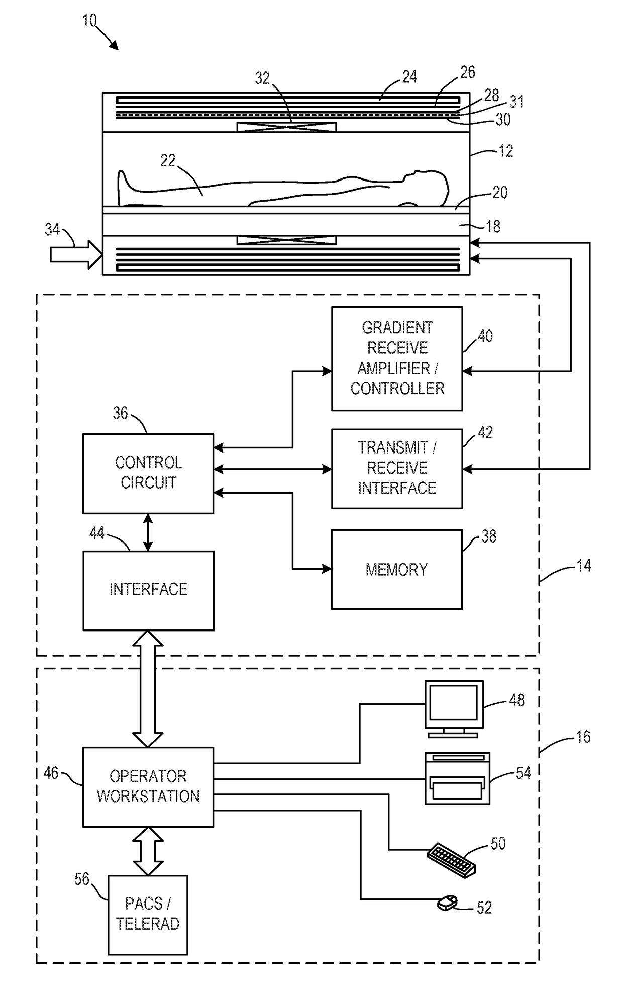
[0014]The following description relates to various embodiments of medical imaging systems. In particular, methods and systems are provided for a foldable radiofrequency (RF) coil array. An example of a magnetic resonance imaging (MRI) system that may be used to acquire images is provided in FIG. 1. The MRI system of FIG. 1 may include one or more foldable RF coil arrays, as illustrated in FIGS. 3A-4B. The one or more foldable RF coil arrays may be comprised RF coils having loop and butterfly geometries, such as the butterfly and loop coils illustrated in FIGS. 2A and 2B. Each RF coil of the foldable RF coil array may be part of a receive circuit that includes a preamplifier, as shown in FIGS. 5-7. The MR signals received by the foldable RF coil array may be used to reconstruct an image of a region of interest according to the method illustrated in FIG. 8.

[0015]As explained previously, MRI imaging systems use RF coils to acquire image information of a region of interest of a scanned ...


PUM


Abstract

In one example, an RF coil array includes a first RF coil configured to generate a magnetic field along a first axis, the first RF coil having a first surface, a second RF coil configured to generate a magnetic field along a second axis, orthogonal to the first axis, the second RF coil having a second surface, and a first foldable interconnect coupling the first RF coil to the second RF coil. The first foldable interconnect may be adjusted to couple the first RF coil to the second RF coil with a first amount of overlap and with the first surface and second surface facing a common direction, or couple the first RF coil to the second RF coil with a second amount of overlap, larger than the first amount of overlap, and with the first surface in face to face position with the second surface.

Description

FIELD[0001]Embodiments of the subject matter disclosed herein relate to non-invasive diagnostic imaging, and more particularly, to magnetic resonance imaging systems.BACKGROUND[0002]Magnetic resonance imaging (MRI) is a medical imaging modality that can create images of the inside of a human body without using x-rays or other ionizing radiation. MRI uses a powerful magnet to create a strong, uniform, static magnetic field. When a human body, or part of a human body, is placed in the main magnetic field, the nuclear spins that are associated with the hydrogen nuclei in tissue water or fat become polarized. This means that the magnetic moments that are associated with these spins become preferentially aligned along the direction of the main magnetic field, resulting in a small net tissue magnetization along that axis. An MRI system also comprises components called gradient coils that produce smaller amplitude, spatially varying magnetic fields when a current is applied to them. Typica...

Claims


Application Information

Patent Timeline
IPC IPC(8): G01R33/34H01F7/20G01R33/36H03H7/40G01R33/30
CPCG01R33/34084H01F7/202G01R33/3614G01R33/30H03H7/40G01R33/3415G01R33/3621G01R33/365H01F5/003H01F7/20
Inventor CHU, DASHENLINDSAY, SCOTT ALLENGUI, DAWEIAKAO, JAMES HIROSHILI, ZHU
Owner GENERAL ELECTRIC CO