Mover system

a moving system and moving wheel technology, applied in the direction of vehicle position/course/altitude control, process and machine control, instruments, etc., can solve the problems of affecting the speed of the entire assembly, the failure of the entire assembly operation, and the interruption or stop of the entire operation, so as to achieve the effect of reducing the pitch between the moving wheel and the moving wheel

Active Publication Date: 2017-11-30
DEXTERITY
View PDF9 Cites 42 Cited by
  • Summary
  • Abstract
  • Description
  • Claims
  • Application Information

AI Technical Summary

Benefits of technology

[0027]In a preferred embodiment each independent mover comprises a pair of coaxially aligned wheels and at least one steering wheel and a cove

Problems solved by technology

If enough packets are lost in a sequence, an entire assembly operation could fail or error.
A problem with many such moving systems, such as chain based systems, is that all the movers and tooling stands must operate at the same line speed.
If a problem is encountered the entire operation can be interrupted or stopped.
Another disadvantage with both chain based or magnet moving systems is that the vector path that the movers travel is essentially mechanically fixed for the life of the machine and is not easily reconfigurable without a major redesign of the entire production system.
In addition, with respect to magnetic moving systems, the rail system must follow the entire vector looped path, which adds expense to the system.
Further, when a bearing begins to wear on one of the movers due to the wheels running along the guiding rail system, there is generally not an easy automated way to remove that mover from a looped configuration without stopping the entire machine for maintenance.
This high rate of speed, particularly around curve sections, increases wear of the support wheels connecting the mover to the rail as well as requiring significant bracing or support of the object to prevent centripetal forces from dislodging or ejecting the object from the mover as it travels along the curve section of the track.
While such robotic movers can be commanded to run at certain speed, they do not operate under a time scheduled control of a motion plan and do not always follow the same path to go to an assigned end point (destination).
Accordingly, the movers of an AGV system do not operate to speed up automatically if they are behind schedule, often caused because a mover's wheels slip on the warehouse floor or if it had to stop and steel around an obstruction on the way to get to the designated end point.
Thus, there is often a significant difference in time between when a mover arrives at a designated end point and when the mover is scheduled to arrive at the end point.
Without such sensors, an AGV mover would often get “los

Method used


Image

  • Mover system
  • Mover system
  • Mover system

Examples


Embodiment Construction

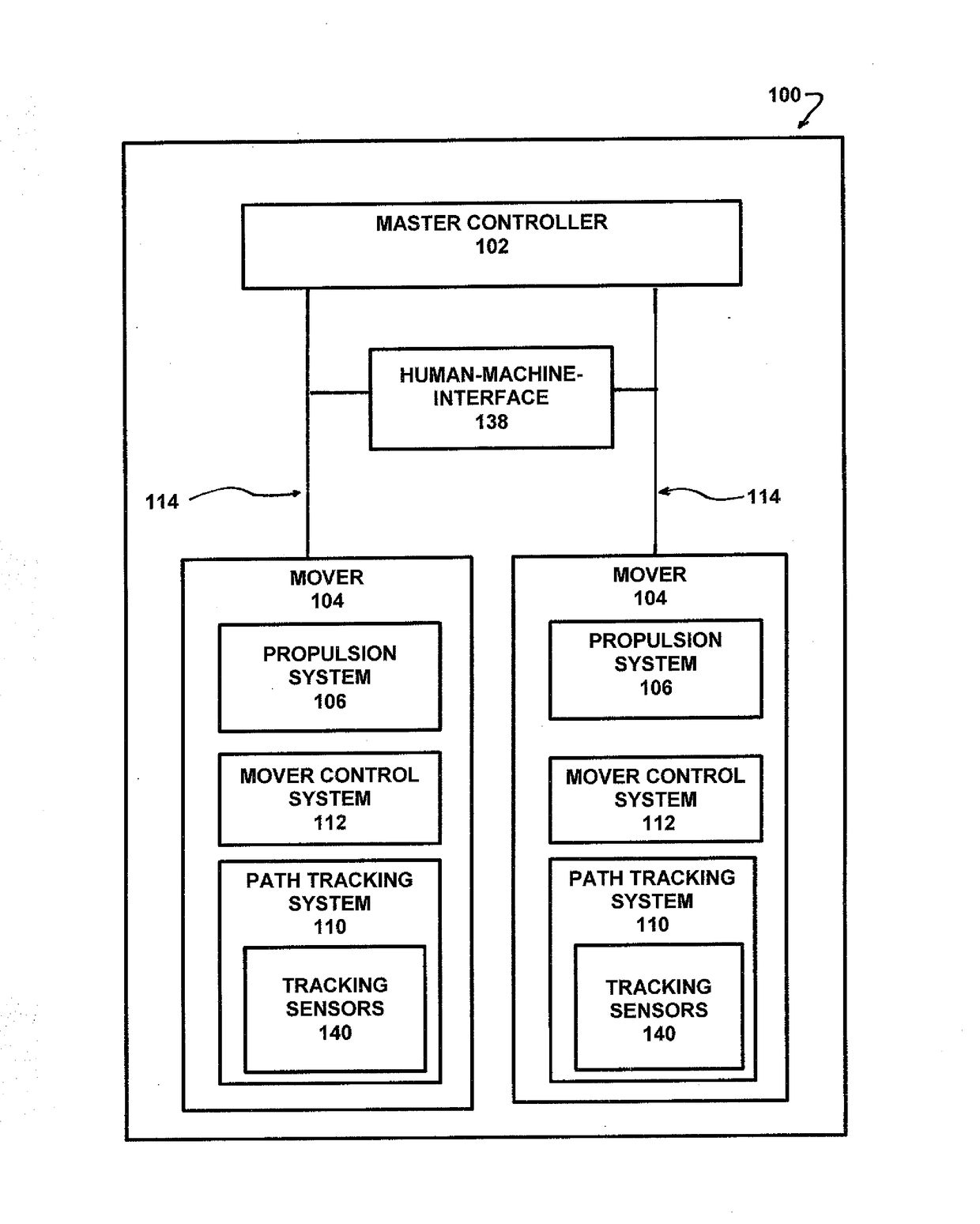
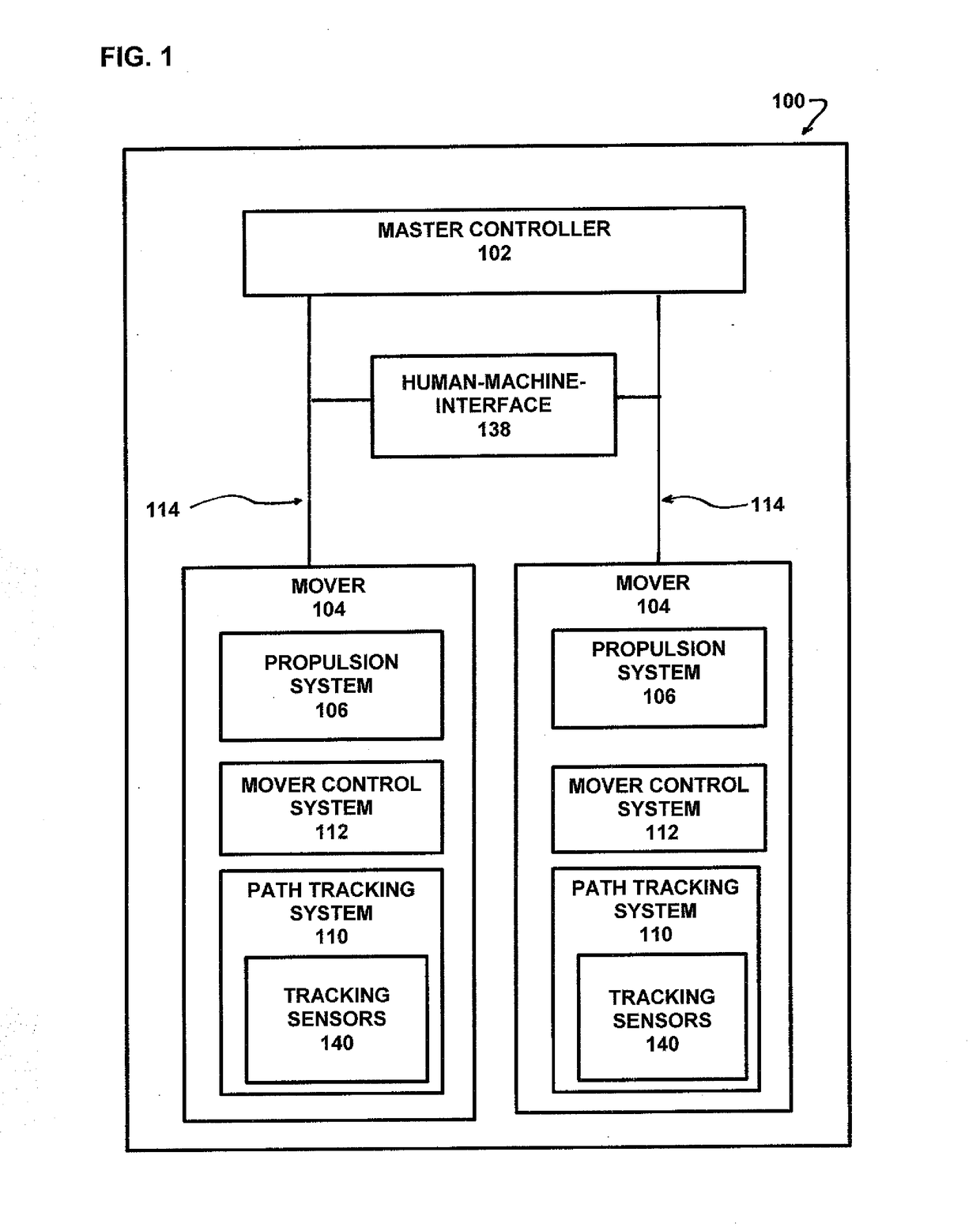
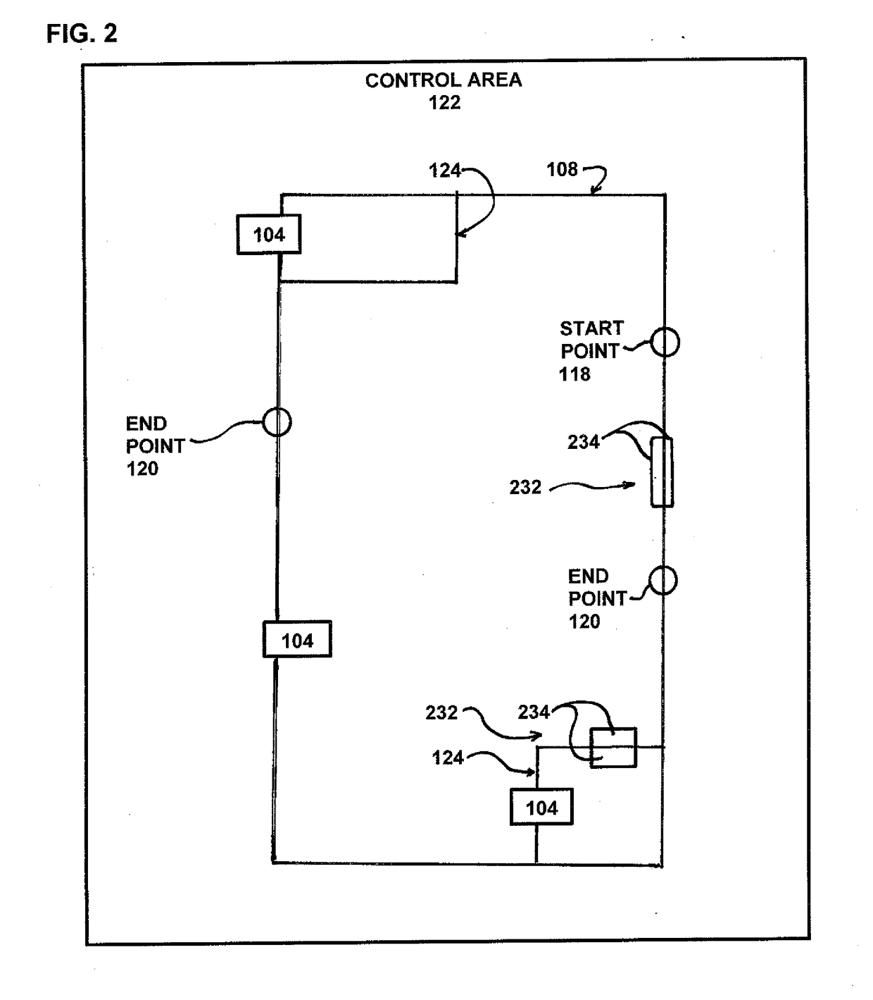
[0079]The subject invention is a new and novel mover system for transporting objects from one location to another location such that each mover arrives at a selected destination at a predetermined scheduled time. In a preferred embodiment of the invention, the mover system is a trackless system whereby independent movers are freely driven along a predefined virtual vector path operating under the direction of a main controller that provides control commands having x and y components. In a preferred embodiment of the invention, each mover operates in forward and reverse velocities and can change directions to transport an object in a simulated assembly closed loop or reciprocating vector path between end points, such as production stations and / or loading and unloading stations, and then follow a return path back to a queuing area before arriving at an initial start point.

[0080]As used herein a platform is an x and y coordinate surface that a mover travels along having a vertical z ax...


PUM


Abstract

A moving system comprising a master controller for monitoring and controlling a master operation comprising one or more individual movers such that each mover arrives at predefined end point at selected times. Each mover includes a mover control system that interacts with the master controller and has a predefined virtual vector path with one or more defined end points. The predefined virtual vector path comprises a plurality of discrete points, wherein each discrete point has a vector axis for use by the master controller and the mover control system to direct the mover to move such that it arrives at each defined end point at a selected time. In operation, the master controller functions to modify the predefined virtual path and sends commands to the mover control system in response to changes in the master operations.

Description

BACKGROUND OF THE INVENTION[0001]The subject application is directed to a mover system for moving objects and more particularly to a mover system for moving objects having a plurality of independently controlled movers operating along an adjustable predetermined pathway.[0002]Mover systems for transporting objects to or from a location historically used humans to directly control the movers, such as carts, forklifts, pallet jacks and overhead cranes. Movers, such as overhead cranes, often used to deliver objects to selected areas within an industrial facility have been automated by gantry systems that typically utilize pulling chains in the X and Y directions to control the path of the objects being transported to a desired location. Many times such automation incorporates rotary motors that operate to adjust the pulling chains while an operator uses levels to target deliveries. In the most automated application of a gantry system, a control system, such as a motion coordinate contr...

Claims


Application Information

Patent Timeline
IPC IPC(8): G05D1/02G05D1/00H04B7/04H04W84/02
CPCG05D1/0212H04W84/02G05D1/0011H04B7/04G05D1/0297G05D2201/0216G05D1/0272B66F9/00G08G1/00
Inventor WERNERSBACH, GLEN C.
Owner DEXTERITY
Why Eureka
Try Eureka