
DTC-Based PLL and Method for Operating the DTC-Based PLL

a phase locked loop and digital converter technology, applied in pulse manipulation, pulse automatic control, pulse technique, etc., can solve the problems of increasing phase noise, negative influence of increasing quantization errors in the system, etc., and achieve the effect of further reducing the influence of dtc quantization, mismatch and nonlinearity errors on pll output spectral purity

Active Publication Date: 2017-11-30
INTERUNIVERSITAIR MICRO ELECTRONICS CENT (IMEC VZW) +2
View PDF12 Cites 25 Cited by
  • Summary
  • Abstract
  • Description
  • Claims
  • Application Information

AI Technical Summary

Benefits of technology

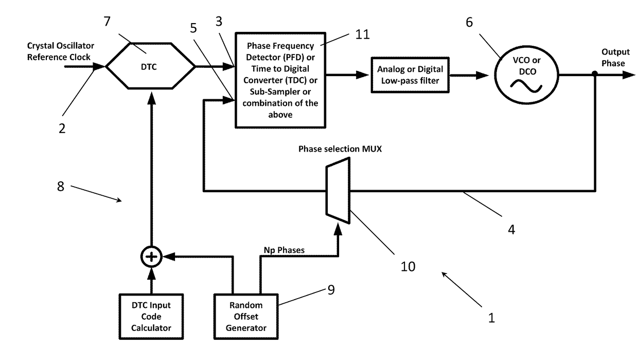
The present patent aims to provide a DTC-based phase locked loop with improved PLL output spectral purity. By adding a pseudo-random number of periods to the delay, the DTC input is randomized, reducing the influence of nonlinearities and quantization errors on the PLL output spectral purity. The patent offers a beneficial and easy means for providing a number of possibilities for randomly generating the offset and delay value, further reducing the influence of DTC errors. This embodiment may also be combined with another embodiment to further increase the number of possibilities for randomizing the offset and delay value.

Problems solved by technology

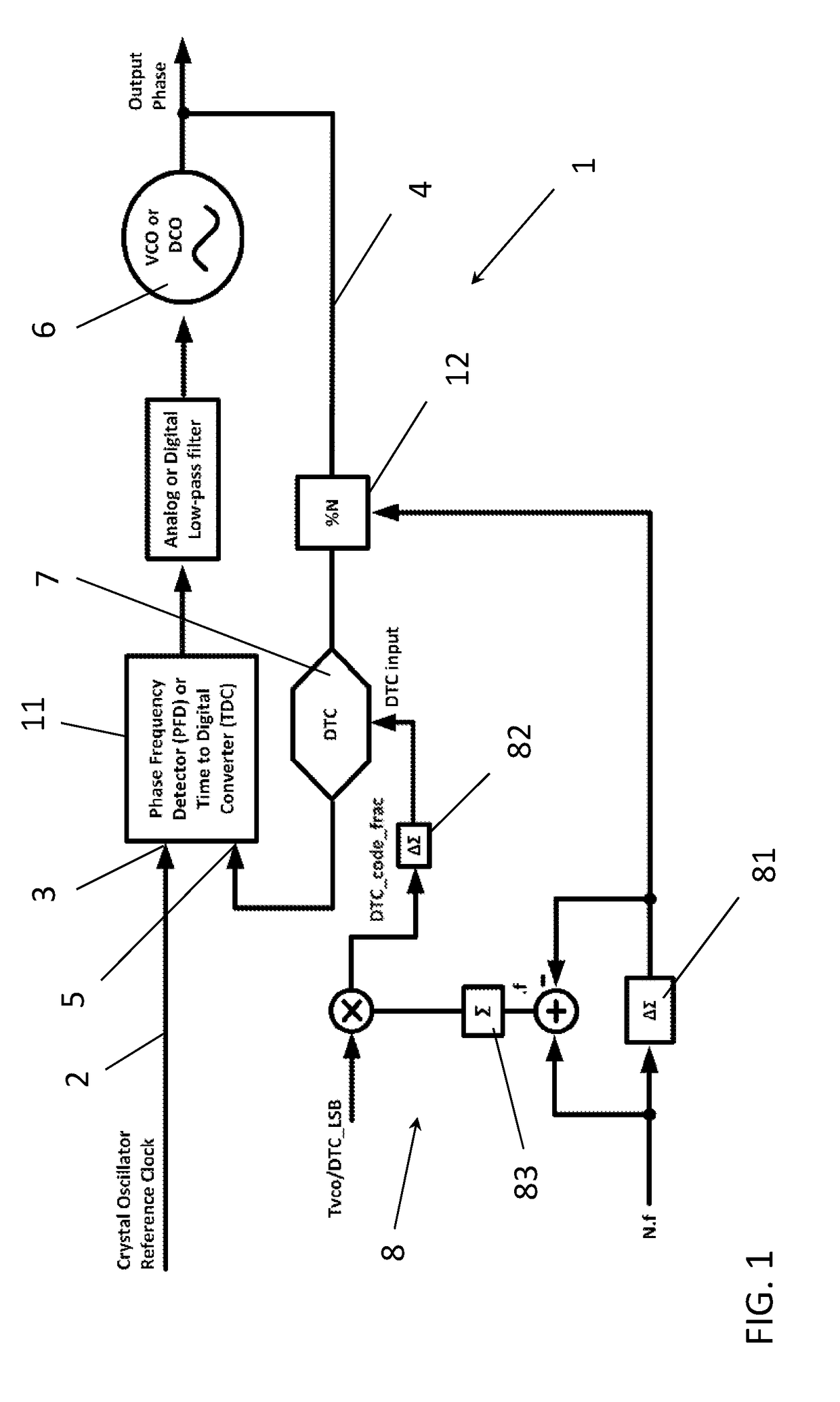
However, the DTC-based PLL 1 has the disadvantage that the DTC 7 introduces quantization, mismatch and nonlinearity errors which negatively influences the PLL output spectral purity by increasing phase noise and spurious content.
However, these solutions have the disadvantage that they increase the quantization errors in the system and thus still have a negative influence on the PLL output spectral purity.

Method used


Image

  • DTC-Based PLL and Method for Operating the DTC-Based PLL
  • DTC-Based PLL and Method for Operating the DTC-Based PLL
  • DTC-Based PLL and Method for Operating the DTC-Based PLL

Examples


Embodiment Construction

[0040]The present disclosure will be described with respect to particular embodiments and with reference to certain drawings but the disclosure is not limited thereto but only by the claims. The drawings described are only schematic and are non-limiting. In the drawings, the size of some of the elements may be exaggerated and not drawn on scale for illustrative purposes. The dimensions and the relative dimensions do not necessarily correspond to actual reductions to practice of the disclosure.

[0041]Furthermore, the terms first, second, third and the like in the description and in the claims, are used for distinguishing between similar elements and not necessarily for describing a sequential or chronological order. The terms are interchangeable under appropriate circumstances and the embodiments of the disclosure can operate in other sequences than described or illustrated herein.

[0042]Moreover, the terms top, bottom, over, under and the like in the description and the claims are use...


PUM


Abstract

The disclosure provides a phase locked loop, PLL, for phase locking an output signal to a reference signal. The PLL comprises a reference path providing the reference signal to a first input of a phase detector, a feedback loop providing the output signal of the PLL as a feedback signal to a second input of the phase detector, a controllable oscillator generating the output signal based on at least a phase difference between reference and feedback signal, a digital-to-time converter, DTC, delaying a signal that is provided at one of the first and second input, a delay calculation path for calculating a DTC delay value. The PLL further comprises a randomization unit for generating and adding a random offset, i.e. a pseudo-random integer, to the delay value. The offset is such that a target output of the phase detector remains substantially unchanged.

Description

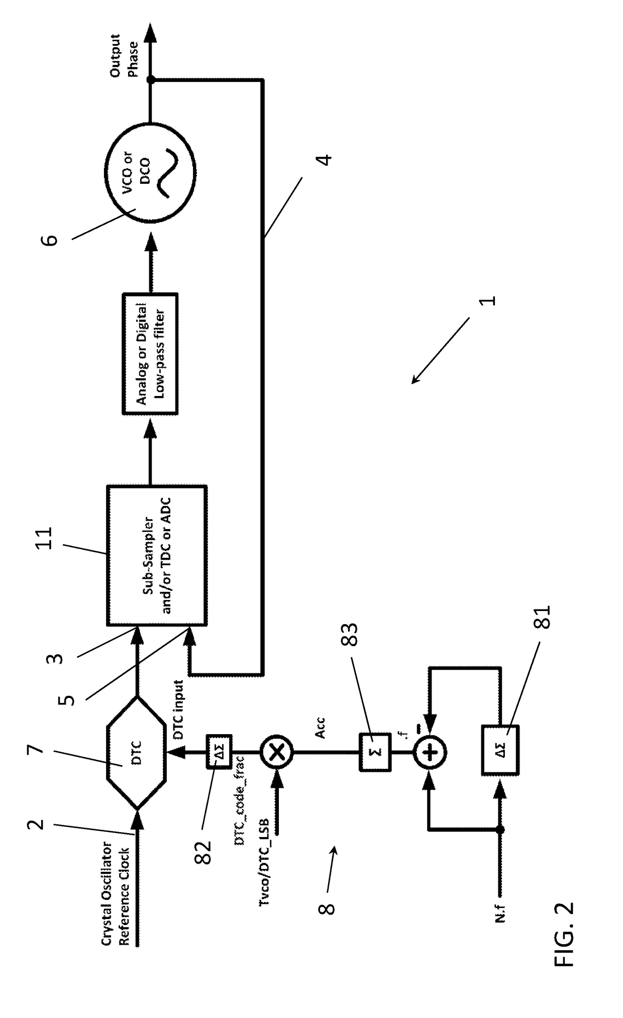
TECHNICAL FIELD[0001]The present disclosure relates to a digital-to-time converter based phase locked loop and to a method for operating a phase locked loop.CROSS REFERENCE TO RELATED APPLICATION[0002]The present disclosure claims priority to European Patent Application No. 16171359.9, filed on May 25, 2016, the contents of which are herein incorporated by reference.BACKGROUND[0003]Digital-to-Time Converter 7 (DTC) based Phase Locked Loops 1 (PLLs) are gaining quickly in importance for LO frequency generation architectures. In context of digital and mixed signal ΔΣ PLLs 1, a DTC 7 can be used for realization of “true fractional dividers” as disclosed in D. Tasca, M. Zanuso, G. Marzin, S. S. C. Levantino and A. L. Lacaita, “A 2.9-4.0-GHz Fractional-N Digital PLL With Bang-Bang Phase Detector and 560-Integrated Jitter at 4.5-mW Power”, in JSSC, 2011 for example. In this disclosure, a DTC 7 is used in the feedback loop 4, which feedback loop 4 also includes the voltage controlled oscil...

Claims


Application Information

Patent Timeline
Patent Type & Authority Applications(United States)
IPC IPC(8): H03L7/085H03K5/159H03L7/099H03K5/00
CPCH03L7/085H03K2005/00013H03K5/159H03L7/0991H03L7/081H03L7/197H03L7/1976H03L2207/50
Inventor MARKULIC, NEREOLIU, YAO-HONGCRANINCKX, JAN
Owner INTERUNIVERSITAIR MICRO ELECTRONICS CENT (IMEC VZW)
Learn More