Method for manufacturing grommet, and grommet

Active Publication Date: 2017-12-07
YAZAKI CORP
View PDF2 Cites 9 Cited by
  • Summary
  • Abstract
  • Description
  • Claims
  • Application Information

AI Technical Summary

Benefits of technology

The invention provides a method for making a grommet that reduces soundproofing costs while maintaining effectiveness. The new method also keeps the grommet's size and weight down. This makes it easier to use and install.

Problems solved by technology

However, such a method makes the grommet larger in size and heavier in weight, and increases costs.

Method used


Image

  • Method for manufacturing grommet, and grommet
  • Method for manufacturing grommet, and grommet
  • Method for manufacturing grommet, and grommet

Examples


modification 1

[0091]FIG. 8 is a perspective view of a grommet according to Modification 1.

[0092]As shown in FIG. 8, convex ribs 25 and 26 for reinforcing the tapered cylindrical peripheral walls 15 and 16 partially are provided to protrude in external surfaces (on wall surfaces) of the peripheral walls 15 and 16 and integrally with the peripheral walls 15 and 16. The ribs 25 and 26 are provided to extend like belts in generatrix directions YS of the external surfaces respectively, and at constant intervals in circumferential directions XR of the peripheral walls 15 and 16 respectively. That is, the ribs 25 and 26 are provided radially in the external surfaces of the tapered cylindrical peripheral walls 15 and 16 respectively. Any number of ribs 25, 26 may be provided as long as it is plural. It is desired to provide three or more ribs 25, 26. In this modification, eight ribs 25, 26 are provided at equal intervals in its circumferential direction XR.

[0093]In this Modification 1, the peripheral wal...

modification 2

[0094]In Modification 2, a ratio between axial lengths of the sound shield space parts S1 and S2 divided by the soundproof wall 20 is defined.

[0095]In a grommet having a sound shield space S internally, sound waves may be cancelled with each other or resonant amplification of the sound waves may occur on the contrary, due to influence of reflection of sound within the sound shield space S. As a result, sound of a frequency to be easily attenuated by the grommet and sound of a frequency to be easily transmitted by the grommet are present.

[0096]For example, conditions in which resonant amplification of sound occurs will be considered using an air column model.

[0097]FIGS. 9A and 9B are views for explaining principles in a case in which axial length of a sound shield space is set, including FIG. 9A which is a view showing conditions in which the sound shield space (using an air column as model) has a function of resonant amplification of sound having a wavelength λ, and FIG. 9B which is...

modification 3

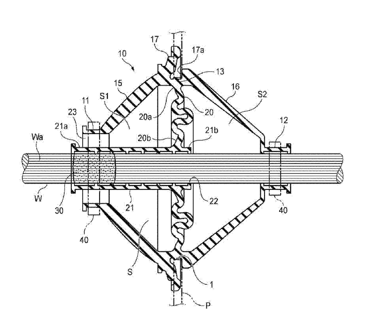
[0115]FIG. 11 is a sectional view of a grommet according to Modification 3. In Modification 3, the soundproof wall 20 is formed into a flat plate-like shape, and the outer circumferential end 20a is connected to the inner circumference of the fitting portion 13. In addition, the inner circumferential end 20b is connected to the cabin side of the inner cylindrical portion 21. Accordingly, the soundproof wall 20 is inclined with respect to a plane perpendicular to the axis of the wire harness W.

[0116]Incidentally, as shown in FIG. 11, a punched groove portion 17b may be formed so that the grommet 10 can be deformed easily when it is pushed by an edge portion of the opening portion 1 of the panel P. Thus, the insertion force to the opening portion 1 of the panel P can be reduced.


PUM


Abstract

A method for manufacturing a grommet, which is fixed to a wire harness W inserted into an opening portion of a panel P and which is fitted and attached to the opening portion to thereby support the wire harness W on the panel P. The grommet includes peripheral walls that surrounds the wire harness W to form a sound shield space S around the wire harness W, and a soundproof wall that is formed in the sound shield space S so as to cross a longitudinal direction of the wire harness W. The soundproof wall is designed by use of an expression of TL=20 log(p×f)−42.5 where TL designates transmission loss of the soundproof wall, ρ designates surface density of the soundproof wall, and f designates a frequency.

Description

CROSS REFERENCE TO RELATED APPLICATIONS[0001]This application is based on and claims priority from Japanese patent application No. 2016-111631 filed on Jun. 3, 2016, the entire contents of which are incorporated herein by reference.BACKGROUND OF THE INVENTION[0002]1. Technical Field[0003]The present invention relates to a method for manufacturing a grommet, and a grommet.[0004]2. Background Art[0005]A grommet in which an air layer is formed internally has been known as a grommet by which a wire harness passing through an opening portion of a panel can be supported on the panel (see Patent Literatures JP-A-2012-125002, JP-A-2001-153270, JP-A-2014-50153, and JP-A-2002-27641).SUMMARY[0006]As described above, in a grommet having an air layer, sound transmitted through the grommet can be suppressed by the air layer. In recent years, a cabin of a vehicle has been requested to have a higher degree of quietness. Thus, the grommet has been also requested to have higher soundproof performance...

Claims


Application Information

Patent Timeline
IPC IPC(8): B60R16/02H02G3/38H01B17/58B60R16/037H01B17/56H02G3/22
CPCB60R16/0222H01B17/583H02G3/38H02G3/22B60R16/0373B60R16/02H01B17/56B60R16/0215H02G3/088
Inventor KATOH, SHINGOKOMINATO, YASUHIRO
Owner YAZAKI CORP
Why Eureka
Try Eureka