Method for operating a redundant automation system

Active Publication Date: 2017-12-07
SIEMENS AG
View PDF4 Cites 35 Cited by
  • Summary
  • Abstract
  • Description
  • Claims
  • Application Information

AI Technical Summary

Benefits of technology

[0004]It is therefore an object of the present invention to provide a method for oper

Problems solved by technology

The complete failure of the automation system is understood to mean that neit

Method used


Image

  • Method for operating a redundant automation system
  • Method for operating a redundant automation system
  • Method for operating a redundant automation system

Examples


Example

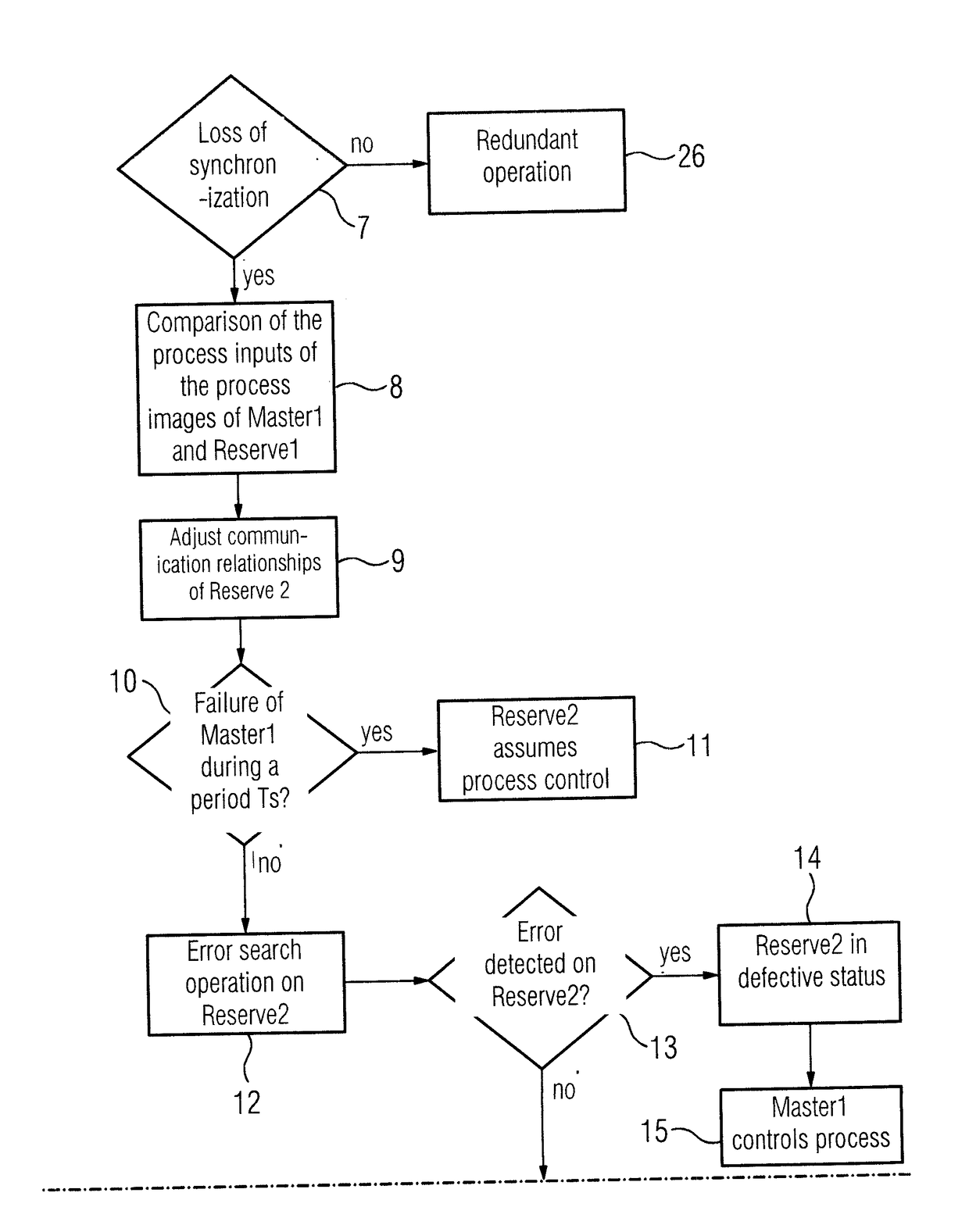
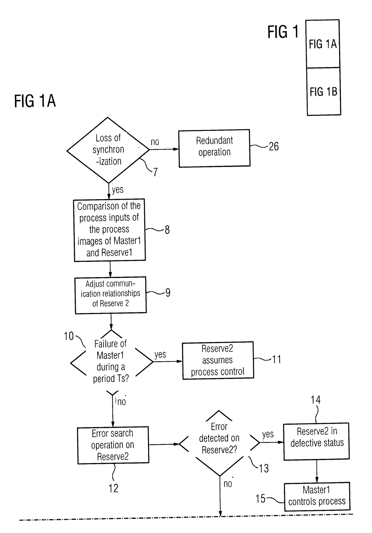
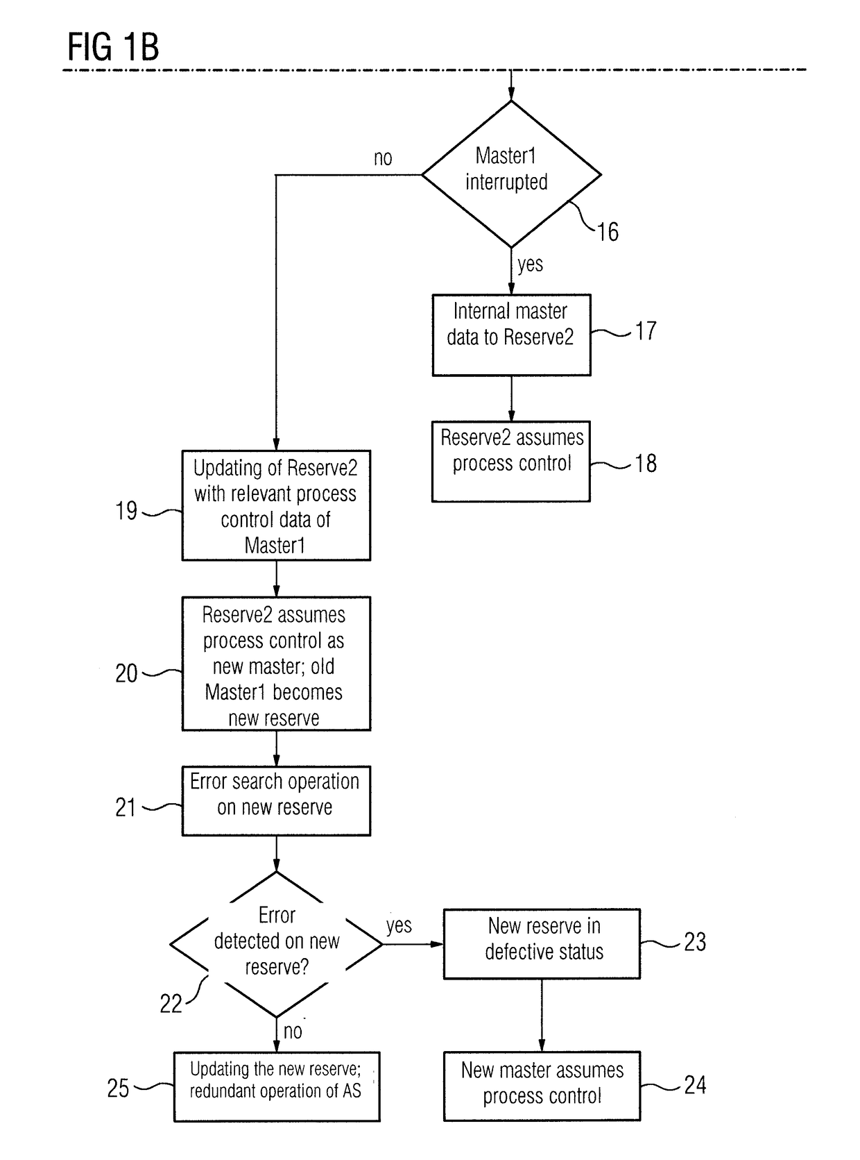
[0014]The same parts in FIGS. 1 and 2 have the same reference characters.

DETAILED DESCRIPTION OF THE EXEMPLARY EMBODIMENTS

[0015]Reference is first made to FIG. 2 which shows a conventional redundant automation system. This has a first and a second subsystem 1, 2 which are connected to peripheral units 4 via a fieldbus 3. The fieldbus 3, for example, complies with the PROFIBUS-DP specification. In principle, other bus systems, such as Ethernet (ProfiNet system redundancy), Modbus or also parallel bus systems are also suitable. The peripheral units 4 receive signals via input lines from transducers or transmitters that serve to acquire a process status, and via output lines output signals to actuators with which the process is influenced. The process and the transducers, detectors and actuators are not shown in the figure for the sake of clarity. The two subsystems 1, 2 process the same control program, where one of the subsystems 1, 2 assumes the master function (mastery) and the oth...


PUM


Abstract

A method for operating a redundant automation system having a plurality of subsystems, wherein one subsystem of the plurality of subsystems operates as a master and assumes process control and the other subsystem operates as a reserve during redundant operation, where measures are provided by which the availability of the redundant automation system is increased, and where regardless of whether transient errors occur on the subsystem of the plurality of subsystems operating as the master or on the subsystem operating as the reserve, a total failure of the automation system is largely avoided.

Description

BACKGROUND OF THE INVENTION1. Field of the Invention[0001]The invention relates to a method for operating a redundant automation system having two subsystems, where one of the subsystems operates as a master and assumes process control and the other subsystem operates as a reserve during redundant operation.2. Description of the Related Art[0002]EP 0 907 912 B1 discloses a method for operating redundant subsystems. Here, two subsystems are coupled in an event-synchronized manner, where at appropriate program points at which provision is made for data synchronization, both subsystems await a response from the other respective participant and only on receiving the response do they each continue their program processing synchronously. However, this often results in synchronization problems when transient errors occur in one of the two subsystems. A possible cause of such temporary errors, which can usually not be localized, may be “bit dumpers” in the main memory, “bit dumpers” in the ...

Claims


Application Information

Patent Timeline
IPC IPC(8): G05B23/02
CPCG05B23/0213G05B23/0289G05B9/03G05B19/0428G05B2219/14131G05B2219/24186
Inventor KLEIFGES, GEORGLAFORSCH, JUERGEN
Owner SIEMENS AG
Why Eureka
Try Eureka