Eureka AIR delivers breakthrough ideas for toughest innovation challenges, trusted by R&D personnel around the world.

Controller, forming machine, and control method

Active Publication Date: 2017-12-07
KOMATSU IND CORP
View PDF10 Cites 0 Cited by
  • Summary
  • Abstract
  • Description
  • Claims
  • Application Information

AI Technical Summary

Benefits of technology

The present invention aims to provide a controller for a forming machine that can easily limit its operation speed. This is done by setting multiple determination areas based on the shape of the bolster and detecting the entry of an object within these areas. The controller can then limit the machine's operation speed based on the determined area, allowing for a simple process without the need for complex calculations. Overall, the invention simplifies the process of controlling the forming machine's speed of operation.

Problems solved by technology

In order to identify the positional coordinates of the finger of the hand, calculate the distance to the dangerous point, and determine whether or not the distance is within a predetermined distance, however, the process may be complicated.

Method used


Image

  • Controller, forming machine, and control method
  • Controller, forming machine, and control method
  • Controller, forming machine, and control method

Examples


Embodiment Construction

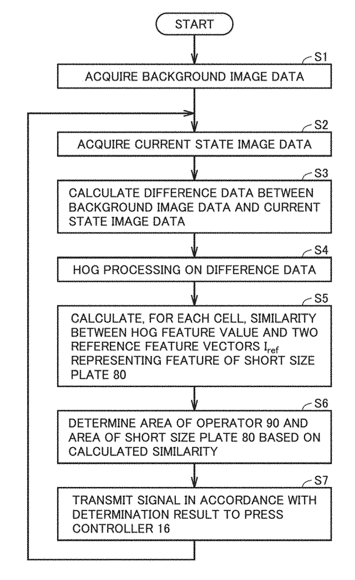
[0068]In the following description, the same components are designated by the same signs. Their names and functions are also identical. Thus, detailed description thereof will not be repeated.

[0069]In this embodiment, a press machine will be described as an example forming machine. In addition, a member having a flat worked surface will be described as an example workpiece to be pressed by the press machine. In particular, a short size plate will be described as an example workpiece.

[0070]It is to be noted that the forming machine is not limited to a press machine, but may be another machine such as a press brake. In addition, the workpiece does not need to have a flat worked surface. It is only required that at least each workpiece to be machined have a certain shape.

A. Overall Configuration

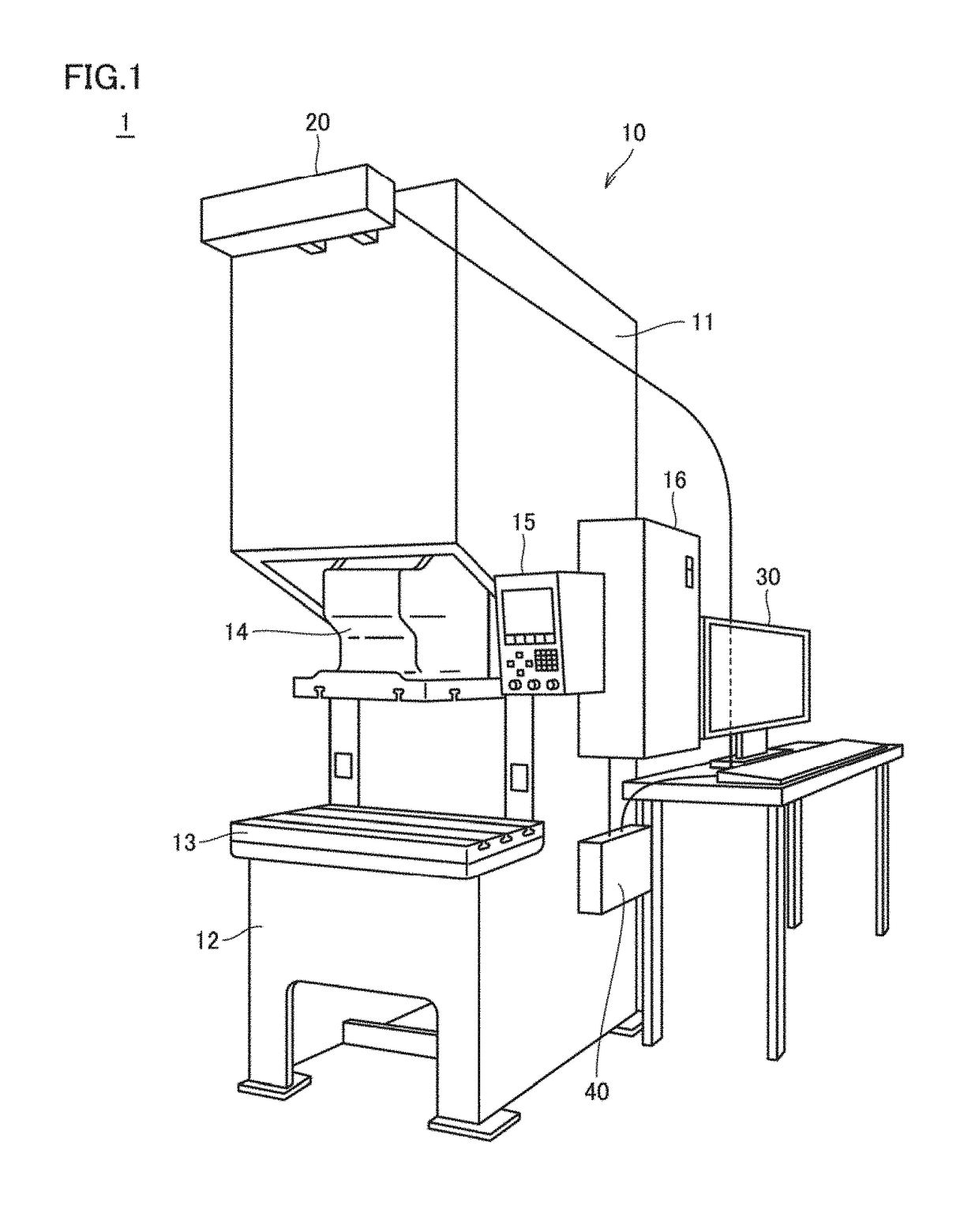
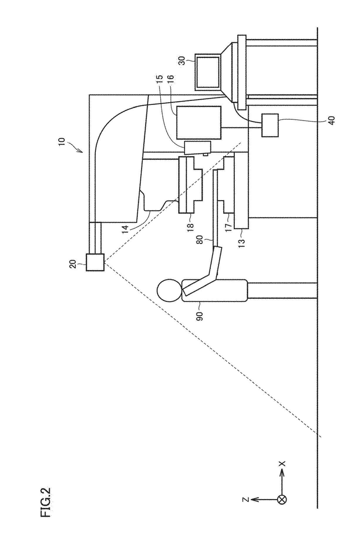
[0071]FIG. 1 is a diagram illustrating the configuration of a press system 1.

[0072]As shown in FIG. 1, press system 1 includes a press machine 10, a sensor 20, an information processor 30, and a...


PUM


Abstract

A controller controls operation of a forming machine capable of forming a workpiece. The controller includes: an object determination unit configured to determine an object other than the workpiece and the forming machine based on image data sensed by a sensor; a setting unit configured to set a plurality of determination areas based on a bolster shape of the forming machine included in the image data; a detection unit configured to detect entry of the object into each of the plurality of determination areas set by the setting unit; and a control unit configured to limit operation speed of the forming machine based on the determination area in which the entry of the object has been detected by the detection unit.

Description

BACKGROUND OF THE INVENTIONField of the Invention[0001]The present disclosure relates to a controller for controlling operation of a forming machine, the forming machine including the controller, and a method for controlling the forming machine.Description of the Background Art[0002]Forming machines such as press machines and press brakes have been conventionally known.[0003]Japanese Patent Laying-Open No. 2008-207253 discloses a press brake in which the position of a finger of an operator is calculated from an image picked up by a CCD camera to compute a distance between the finger and a ram, and if the distance is too short, operation speed of the ram is limited.SUMMARY OF THE INVENTION[0004]Japanese Patent Laying-Open No. 2008-207253 describes a configuration of calculating the distance from positional coordinates of the finger of a hand of the operator to a dangerous point, and if it is determined that the finger interferes with the ram, controlling the operation speed.[0005]In ...

Claims


Application Information

Patent Timeline
IPC IPC(8): G06T7/00G06K9/62G06K9/46G06K9/52
CPCG06T7/0008G06T7/0044G06T7/0081G06K9/4642G06T2207/20021G06K9/52G06T2207/30164G06K2209/19G06K9/6215G06T7/11G06T2207/20224G06T7/254G06T7/194G06V20/52G06V2201/06
Inventor WATANABE, TETSUYOUKOBAYASHI, TAKESHIYAMASHITA, SHUHEI
Owner KOMATSU IND CORP
Why Eureka
Eureka Blog
Learn More