Touch panel, electronic device including same, and method for manufacturing touch panel

a technology of electronic devices and touch screens, applied in electronic switching, pulse techniques, instruments, etc., can solve the problems of undesirable thickness, inconvenient manufacturing, and inability to meet the needs of users, so as to reduce external light reflectivity, reduce the thickness of electronic devices, and increase the aperture ratio of touch screens.

Active Publication Date: 2017-12-07
SAMSUNG DISPLAY CO LTD
View PDF26 Cites 20 Cited by
  • Summary
  • Abstract
  • Description
  • Claims
  • Application Information

AI Technical Summary

Benefits of technology

[0009]A touch panel constructed according to the principles of the invention and an electronic device including the same are capable of preventing touch sensors incorporated in the device from being viewed due to the reflection of external light by reducing external light reflectivity, e.g., through a darkening layer. Various exemplary embodiments of the invention may also decrease the thickness of an electronic device having a touch screen as compared to conventional devices and / or increase the aperture ratio of the pixels of the touch screen. The foregoing benefits may be achieved simultaneously in some embodiments.

Problems solved by technology

The visibility of the touch sensors is undesirable.
For example, when the touch sensors visibly reflect external light, this light interferes with the visibility of content displayed on the touch screen.
The thickness is undesirable because, for example, it adds weight and expense to the device and adds inconvenience to carry, use and handle the device.
In other words, the attempt to reduce the reflection of external light may also inhibit the visibility of desirable light produced by the touch screen by reducing the viewing angle through which light may be emitted.

Method used


Image

  • Touch panel, electronic device including same, and method for manufacturing touch panel
  • Touch panel, electronic device including same, and method for manufacturing touch panel
  • Touch panel, electronic device including same, and method for manufacturing touch panel

Examples


Embodiment Construction

[0058]In the following description, for the purposes of explanation, numerous specific details are set forth in order to provide a thorough understanding of various exemplary embodiments. It is apparent, however, that various exemplary embodiments may be practiced without these specific details or with one or more equivalent arrangements. In other instances, well-known structures and devices are shown in block diagram form in order to avoid unnecessarily obscuring various exemplary embodiments.

[0059]In the accompanying figures, the size and relative sizes of layers, films, panels, regions, etc., may be exaggerated for clarity and descriptive purposes. Also, like reference numerals denote like elements.

[0060]When an element or layer is referred to as being “on,”“connected to,” or “coupled to” another element or layer, it may be directly on, connected to, or coupled to the other element or layer or intervening elements or layers may be present. When, however, an element or layer is re...


PUM

PropertyMeasurementUnit
light reflectivityaaaaaaaaaa
refractive indexaaaaaaaaaa

Abstract

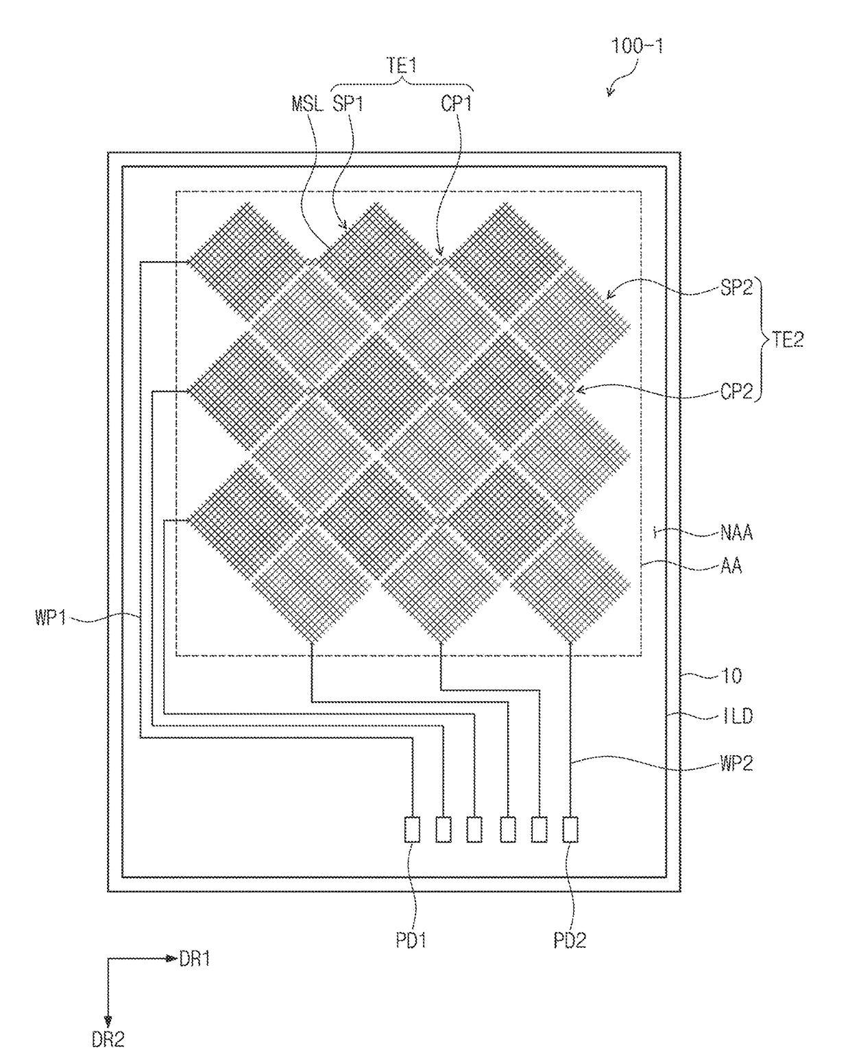
A touch panel is manufactured by a method that decreases undesirable reflections of external light while improving the visibility of emitted light. The touch panel includes a base layer including an active region responsive to an external touch to generate an electronic signal and a peripheral region adjacent to the active region, and a first conductive pattern disposed on the active region and a second conductive pattern disposed on the peripheral region, each of the first conductive pattern and the second conductive pattern including a conductive layer having an external light reflectivity and a darkening layer disposed over the conductive layer. External light reflectivity of each of the first and second conductive patterns is lower than that of the conductive layer.

Description

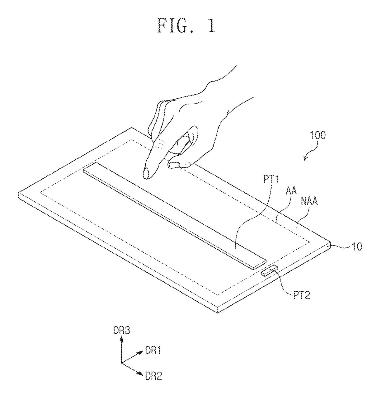
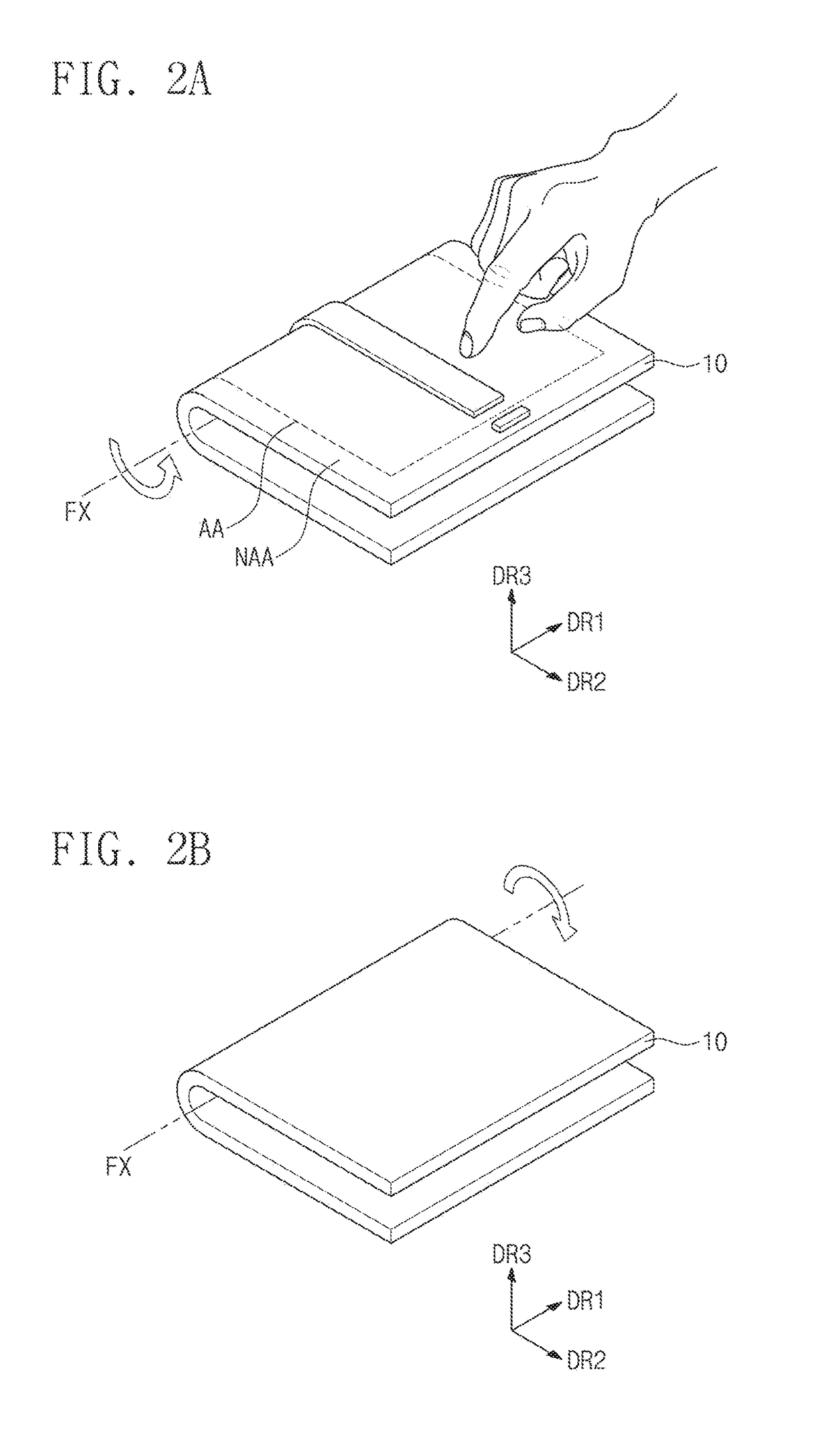
CROSS-REFERENCE TO RELATED APPLICATION[0001]This application claims priority from and the benefit of Korean Patent Application No. 10-2016-0068366, filed on Jun. 1, 2016, which is hereby incorporated by reference for all purposes as if fully set forth herein.BACKGROUNDField[0002]Exemplary embodiments employing the inventive concepts relate generally to a touch panel, an electronic device including the same, and a method for manufacturing a touch panel, and more particularly, to a touch panel with decreased pattern visibility, an electronic device including the same, and a method for manufacturing the touch panel.Discussion of the Background[0003]Electronic devices are activated by applied electrical signals. Electronic devices may include a touch screen for sensing a touch applied from outside the electronic device, and a display apparatus for displaying an image, where the display apparatus also is able to sense a touch applied from outside the electronic device.[0004]The electroni...

Claims


Application Information

Patent Timeline
Patent Type & Authority Applications(United States)
IPC IPC(8): H03K17/96G06F3/044C23F1/00G06F3/041
CPCH03K17/962G06F3/0412G06F3/044G06F2203/04103G06F2203/04111G06F2203/04112C23F1/00G06F2203/04102G06F3/0446G06F3/0445G06F3/041G06F3/0416H05K3/0017H05K3/00
Inventor KIM, KYUNGSEOPJUNG, HANYUNGHAN, SANGYOUNPARK, YONGWOO
Owner SAMSUNG DISPLAY CO LTD
Why Eureka
Try Eureka