Cutting head for a string trimmer

a cutting head and string trimmer technology, applied in the field of string trimmer, can solve the problems of spool housing wear, difficult to establish the proper balance of forces within the spool, and difficulty in feeding out lines when not needed, and achieve the effect of more reliable system

Active Publication Date: 2017-12-14
BLACK & DECKER INC
View PDF2 Cites 5 Cited by
  • Summary
  • Abstract
  • Description
  • Claims
  • Application Information

AI Technical Summary

Benefits of technology

[0005]It is therefore an object of the present invention to provide a string trimmer with a line feed mec...

Problems solved by technology

The problem with this method is that it requires the user to regularly bang the spool housing on the ground, which wears out the spool housing.
Furthermore, accidental line feeding occurs when the user inadvertently bangs the string trimmer on the ground, thus feeding out line when not needed and leading to waste.
The problem with these automatic feed systems is they are very delicate and establishing the proper balance of forces within the spo...

Method used


Image

  • Cutting head for a string trimmer
  • Cutting head for a string trimmer
  • Cutting head for a string trimmer

Examples


Embodiment Construction

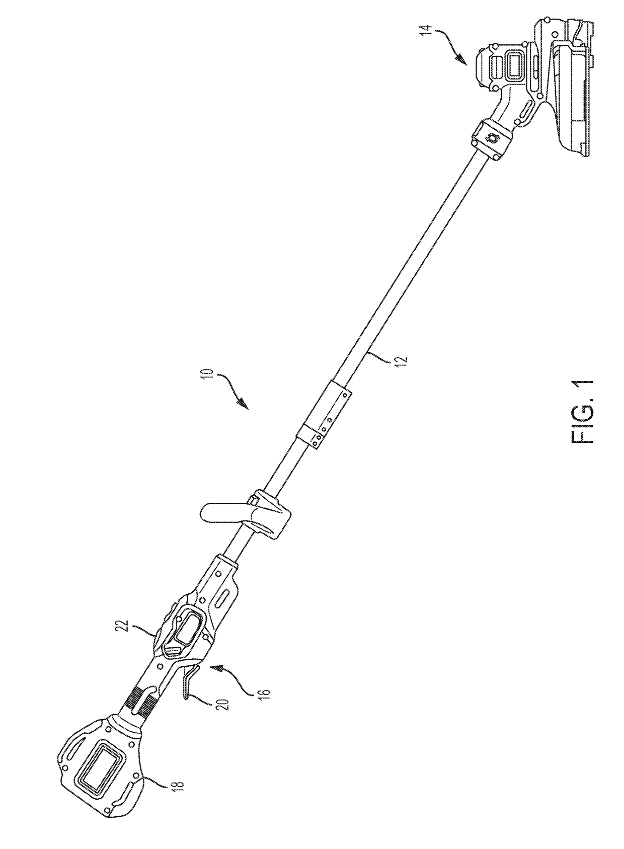
[0022]FIG. 1 shows a string trimmer 10 in accordance with an embodiment of the invention. The string trimmer includes a shaft 12 having a working head 14 on a first forward end, and a handle 16 on a second rearward end. To the rear of the handle 16 is a battery housing 18 for holding a battery to power a motor. It should be understood that AC power may be used as well and still fall within the scope of the invention. The handle 16 includes a trigger 20 to actuate the motor and a button 22 to initiate the line feed, as will be further explained later.

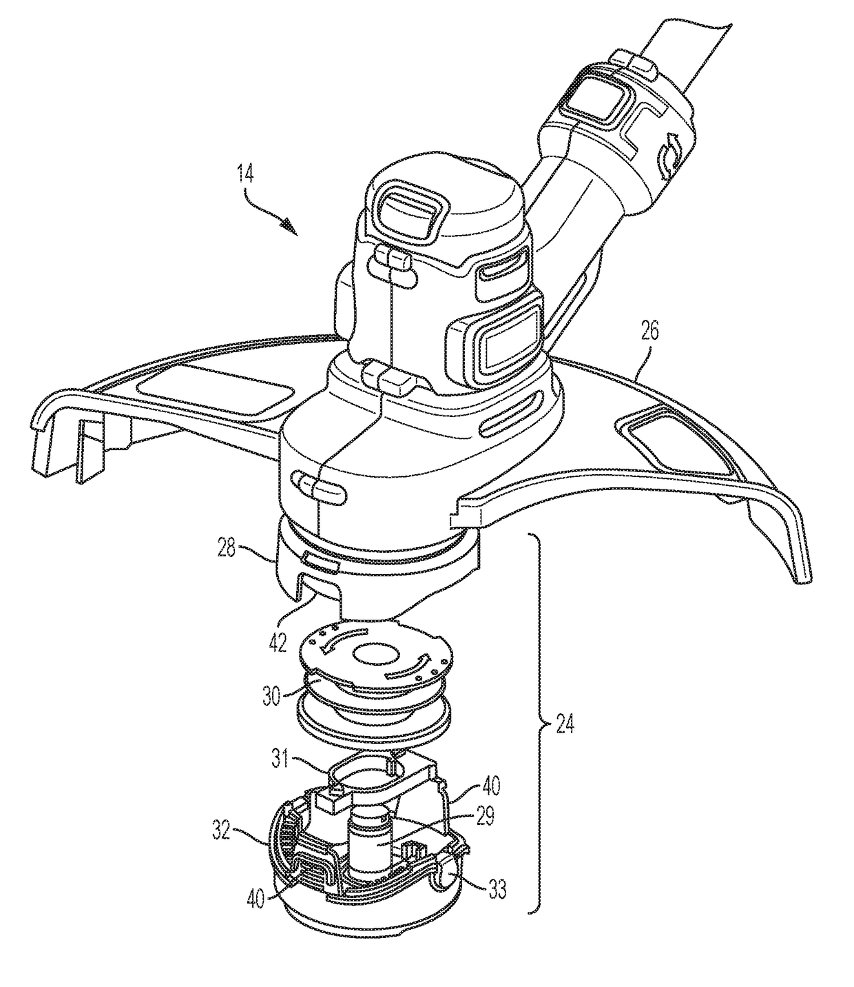
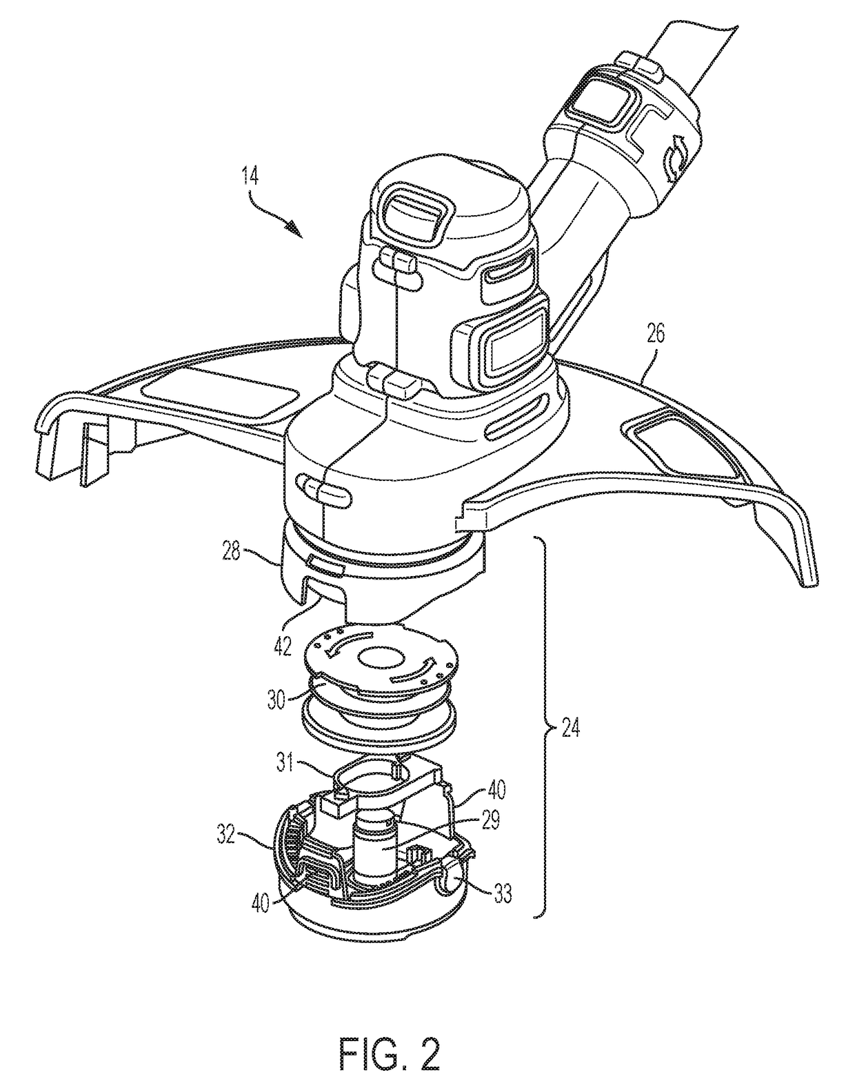
[0023]Now referring to FIGS. 2 and 3, the working head 14 houses the motor 15, and includes a spool assembly 24 and a guard 26 to shield the user from flying debris. The spool assembly 24 includes a spool housing 28, a spool 30 housed in the spool housing, and a spool cap 32. Also included is a lever 31 that locks and releases the spool 30 relative to the spool cap 32 to feed out cutting line. The spool cap 32 includes tabs 40 that engag...


PUM


Abstract

The present invention is directed to a string trimmer line feeding mechanism having a sliding lever that locks a spool relative to the spool housing, and only feeds additional cutting line when the user actuates a button. This brakes a motor, which generates a force acting on the spool to move the lever into an unlocked position, allowing the spool to rotate relative to the spool housing and feed additional cutting line.

Description

FIELD OF THE INVENTION[0001]The present invention discloses a string having a cutting head with an improved line feed mechanism.BACKGROUND OF THE INVENTION[0002]Existing string trimmers use a flexible line spinning at high speeds to cut vegetation. The line is often made of a plastic or similar material that is gradually worn down during use. As the line shortens, additional line is released from a spool to maintain a minimal line length for proper operation.[0003]Existing line feed mechanisms for string trimmers fall into two general categories; bump feed and automatic line feed systems. Bump feed systems require the user to bump the working head on the ground, which causes the spool to be release from a locked position so that additional line is fed. The problem with this method is that it requires the user to regularly bang the spool housing on the ground, which wears out the spool housing. Furthermore, accidental line feeding occurs when the user inadvertently bangs the string t...

Claims


Application Information

Patent Timeline
IPC IPC(8): A01D34/416
CPCA01D34/4167A01D34/4163A01D34/4162
Inventor PALERMO, JOHN
Owner BLACK & DECKER INC
Why Eureka
Try Eureka