Foreign body removal device and drive device for foreign body removal device
a technology for foreign bodies and drives, applied in vehicle maintenance, vehicle cleaning, television systems, etc., can solve problems such as interruption of checking, blurred video displayed on the display, etc., and achieve the effect of preventing the occurrence of abnormal sound and improving the degree of wiring freedom
- Summary
- Abstract
- Description
- Claims
- Application Information
AI Technical Summary
Benefits of technology
Problems solved by technology
Method used
Image
Examples
first modified embodiment
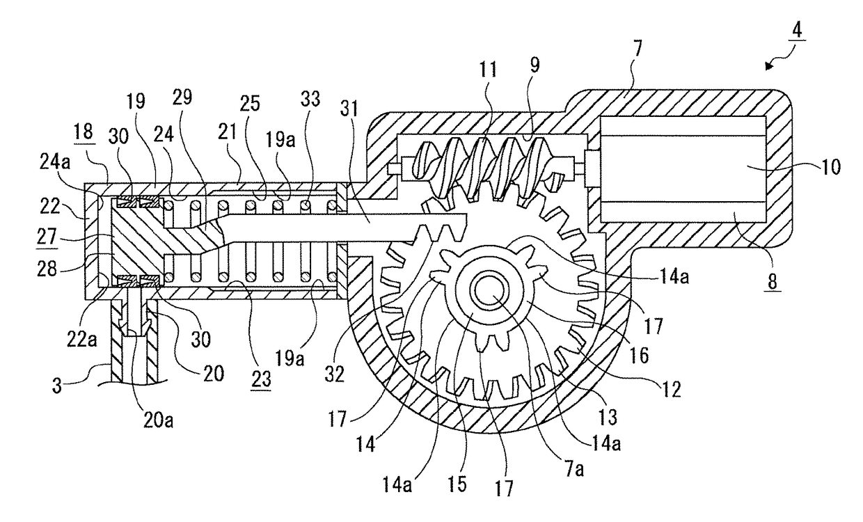
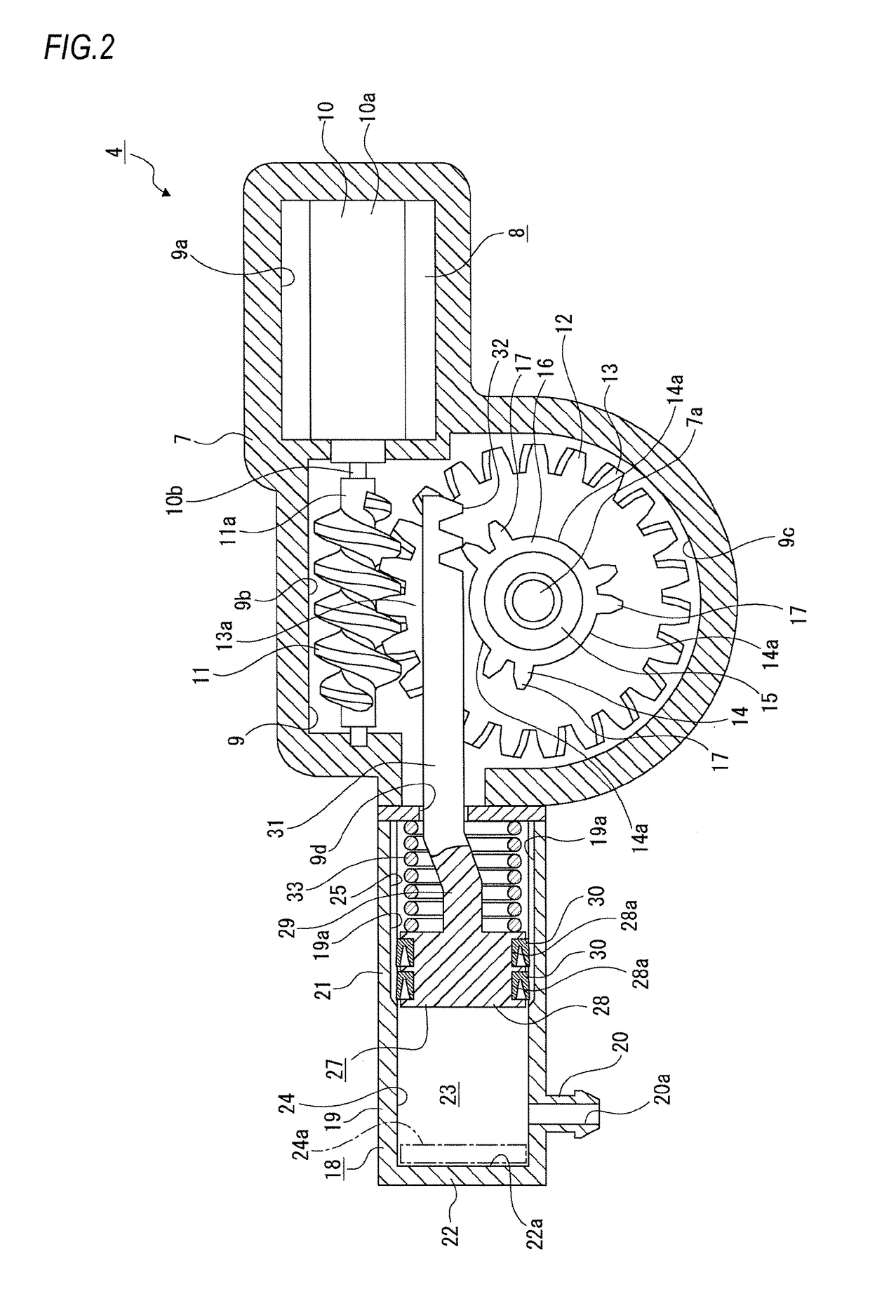
[0122]First, a moving mechanism 8A of a first modified embodiment is described (refer to FIG. 11).
[0123]The moving mechanism 8A includes a motor 10A and a pinion 14A.
[0124]The motor 10A has a main body part 10a and a motor shaft 10b. The motor shaft 10b is arranged in a direction orthogonal to the moving direction of the rack 31.
[0125]The pinion 14A is fixedly coupled to the motor shaft 10b and functions as the main driving gear. The pinion 14A has the same configuration as the pinion 14 and includes the annular part 16 and the gear parts 17, 17, 17, and parts of the pinion between the gear parts 17, 17, 17 are respectively formed as the toothless parts 14a, 14a, 14a.
[0126]The rack part 32 of the rack 31 is formed as the driven gear, and the rack part 32 is configured to be engageable with the gear part 17 of the pinion 14A.
[0127]In the configuration where the moving mechanism 8A is provided, when the motor 10A starts to drive, the gear part 17 of the pinion 14A is engaged with the...
second modified embodiment
[0130]Subsequently, a moving mechanism 8B of a second modified embodiment is described (refer to FIG. 12).
[0131]The moving mechanism 8B has a motor 10B, a transmission gear 34 and an actuating gear 35.
[0132]The motor 10B has a main body part 10a and a motor shaft 10b. The motor shaft 10b is arranged in a direction orthogonal to the moving direction of the rack 31.
[0133]The transmission gear 34 is a spur gear, is fixedly coupled to the motor shaft 10b and functions as the main driving gear.
[0134]The actuating gear 35 functions as the driven gear, and is made by integrally forming a spur gear 36 and a pinion 14B protruding laterally from a central portion of the spur gear 36. The actuating gear 35 is supported at a central portion thereof to a support shaft part 7a of a case body 7B via the bearing 15.
[0135]The spur gear 36 is engaged with the transmission gear 34.
[0136]The pinion 14B is arranged concentrically with the spur gear 36 and has the same configuration as the pinion 14.
[013...
third modified embodiment
[0142]Subsequently, a moving mechanism 8C of a third modified embodiment is described (refer to FIG. 13).
[0143]The moving mechanism 8C is configured by a solenoid 37.
[0144]The solenoid 37 includes a driving shaft 38 extending in the front and rear direction and a coil 39 in which the driving shaft 38 is inserted. The driving shaft 38 is an iron core, for example.
[0145]In the configuration where the moving mechanism 8C is provided, the rack 31 is not provided and the driving shaft 38 is coupled to the coupling part 29 of the piston 27.
[0146]In the configuration where the moving mechanism 8C is provided, when the coil 39 is energized and thus the solenoid 37 starts to drive, the driving shaft 38 and the piston 27 are integrally moved in the force accumulation direction against the urging force of the urging spring 33.
[0147]When the energization to the coil 39 is stopped at a predetermined position, the driving shaft 38 and the piston 27 are moved in the delivery direction at higher sp...
PUM
 Abstract
Description
Claims
Application Information
 - R&D
- Intellectual Property
- Life Sciences
- Materials
- Tech Scout
- Unparalleled Data Quality
- Higher Quality Content
- 60% Fewer Hallucinations
Browse by: Latest US Patents, China's latest patents, Technical Efficacy Thesaurus, Application Domain, Technology Topic, Popular Technical Reports.
© 2025 PatSnap. All rights reserved.Legal|Privacy policy|Modern Slavery Act Transparency Statement|Sitemap|About US| Contact US: help@patsnap.com


