
LED bulb structure

a technology of led bulbs and glass envelopes, applied in the direction of lighting device details, light sources, lighting and heating apparatus, etc., can solve the problems of affecting the use of led bulbs

Inactive Publication Date: 2017-12-14
LIN CHIN SAN
View PDF1 Cites 16 Cited by
  • Summary
  • Abstract
  • Description
  • Claims
  • Application Information

AI Technical Summary

Benefits of technology

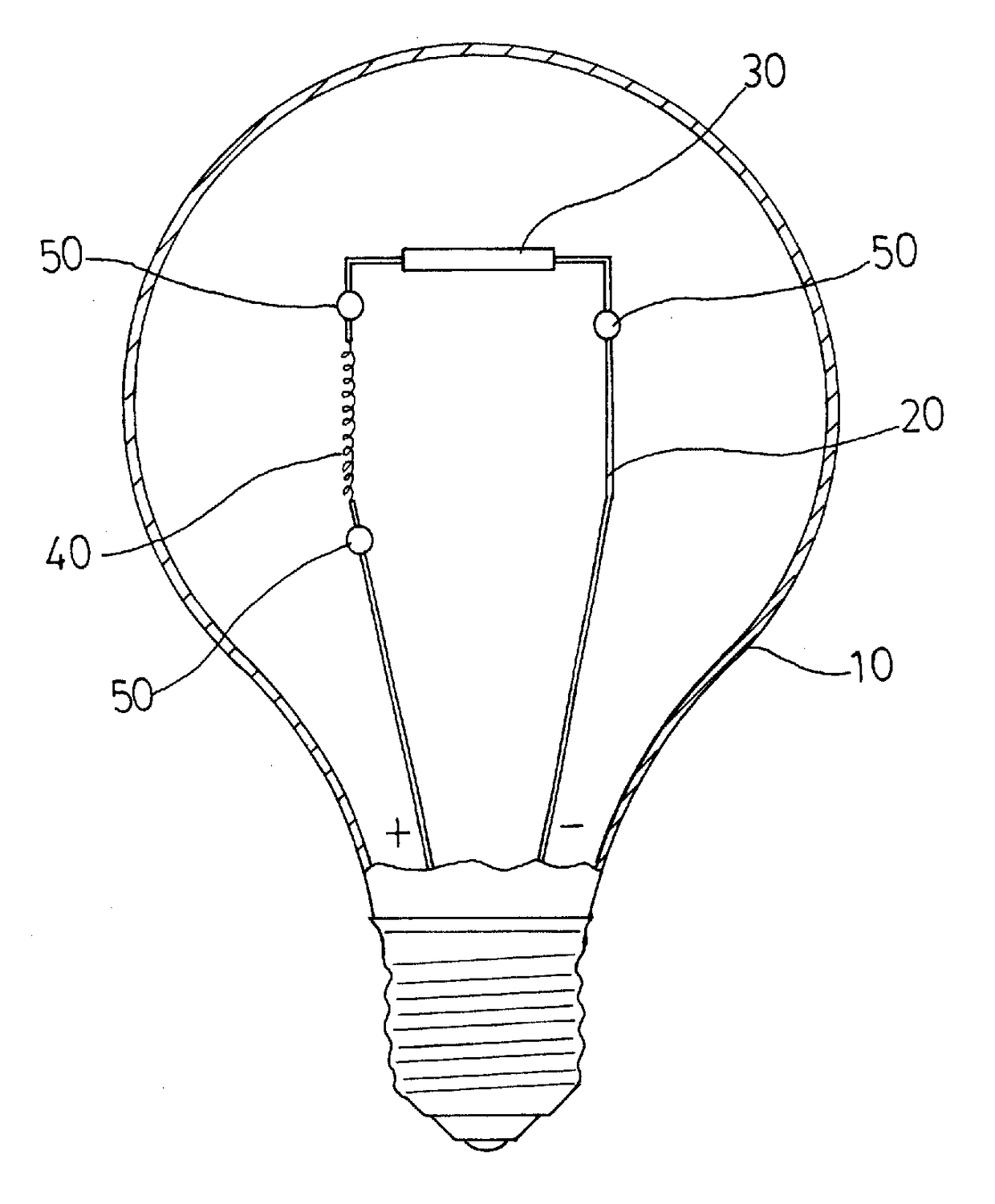
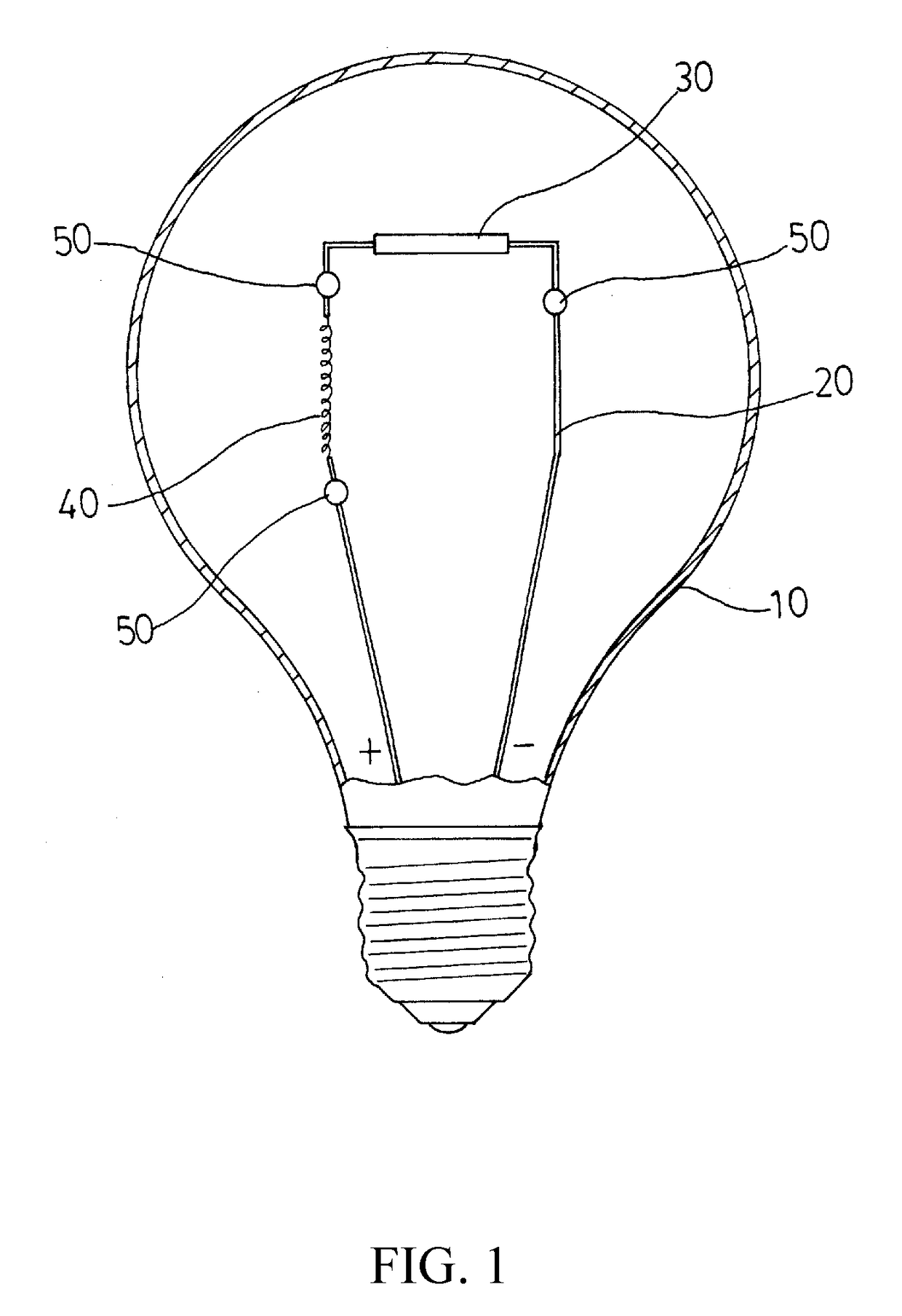
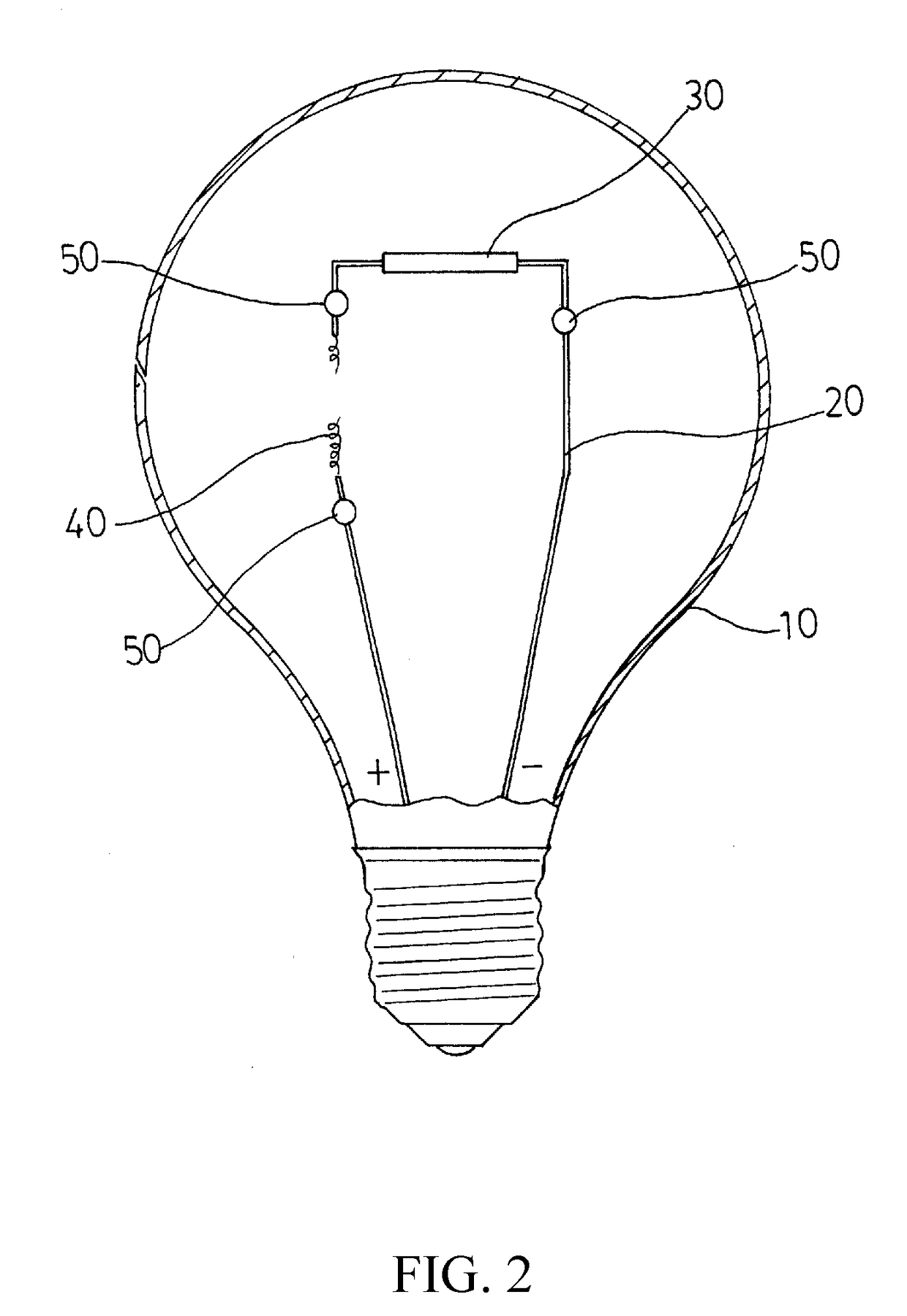
This patent describes an LED light bulb structure that includes a glass envelope, support, LED light emitting body, tungsten filament light emitting body, and electronic element units. The glass envelope is either vacuum-sealed with gas or not. The support is fixed inside the glass envelope, and both the LED light emitting body and tungsten filament light emitting body are connected to the support. The necessary electronic element units are configured on the support between the LED light emitting body and tungsten filament light emitting body. The support has a positive pole and negative pole. When a power source is turned on, the LED light emitting body will emit light through the tungsten filament light emitting body. However, if the power source is turned off, the tungsten filament will burn and melt or break due to the high temperature caused by molecular oxygen oxidation combustion, leaving the support open to interrupt the power source and causing the LED light emitting body to extinguish, reminding users to replace it with a new one.

Problems solved by technology

But, if the glass envelope of such kind of LED bulb is broken and is still lighted up without replacement due to negligence or unawareness, probably resulting in electricity leakage due to the inflow of water and cutting people due to the broken parts of the glass envelope.
Therefore, conventional LED bulb structures with a glass envelope are still not ideal, required to improve.

Method used


Image

  • LED bulb structure
  • LED bulb structure
  • LED bulb structure

Examples


Embodiment Construction

[0006]Referring to FIG. 1, an LED bulb structure of the present invention is mainly constituted by a glass envelope 10, support 20, LED light emitting body 30, tungsten filament light emitting body 40 and electronic element units 50, where the glass envelope 10 is vacuum-sealed and is filled with gas (a uncertain amount of inert gas) or no gas. The support 20 formed by a conducting line is fixed inside the glass envelope 10, both the LED light emitting body 30 and tungsten filament light emitting body 40 are connected with the support 20, and the necessary electronic element units 50 are configured on the support 20 between the LED light emitting body 30 and tungsten filament light emitting body 40. Furthermore, one side of the support 20 is set to a positive pole and another negative pole. As arranged, one side of power source (positive pole or negative pole) must be turned on to light LED light emitting body 30 through the tungsten filament light emitting body 40, while the tungst...


PUM


Abstract

An LED bulb structure includes a glass envelope, support, LED light emitting body, tungsten filament light emitting body and electronic element units, where the glass envelope is vacuum-sealed, the support formed by a conducting wire is fixed inside it, both LED and tungsten filament light emitting bodies are configured on the support, the necessary electronic element units are configured on the support between the LED light emitting body and tungsten filament light emitting body, and one side of the support is set to a positive pole and another side thereof a negative pole. As arranged, air will enter the glass envelope of a broken LED bulb to cause the tungsten filament to be burned to break to extinguish, and thus to cause the LED light emitting body to extinguish in such a way to remind users that the broken LED bulb must be replaced with a new one.

Description

TECHNICAL FIELD OF THE INVENTION[0001]The present invention relates to an LED bulb structure, and more particularly to an LED Christmas bulb or general lighting bulb structure.DESCRIPTION OF THE PRIOR ART[0002]LED bulbs mentioned in this specification are Christmas bulbs or general lighting bulbs with a glass envelope. Such kinks of LED bulbs available in the current market are only installed with one or more LED light emitting bodies for light emitting purpose. But, if the glass envelope of such kind of LED bulb is broken and is still lighted up without replacement due to negligence or unawareness, probably resulting in electricity leakage due to the inflow of water and cutting people due to the broken parts of the glass envelope. Therefore, conventional LED bulb structures with a glass envelope are still not ideal, required to improve.SUMMARY OF THE INVENTION[0003]An LED bulb structure of the present invention is mainly constituted by a glass envelope, support, LED light emitting ...

Claims


Application Information

Patent Timeline
IPC IPC(8): F21K9/238F21V3/04F21K9/232F21V25/04
CPCF21K9/238F21V3/0418F21Y2115/10F21K9/232F21V25/04F21V3/061H01K1/02H01K1/16H01K1/62
Inventor LIN, CHIN-SAN
Owner LIN CHIN SAN
Learn More