Adaptive laser power and ranging limit for time of flight sensor

a technology of time-of-flight sensor and adaptable laser power, which is applied in the direction of measurement devices, instruments, and devices using reradiation, can solve the problems of limiting the duration of laser output, and achieve the effects of increasing the range of the device, reducing the power consumed by the device, and increasing the accuracy of distance determination

Active Publication Date: 2017-12-14
STMICROELECTRONICS SRL
View PDF27 Cites 44 Cited by
  • Summary
  • Abstract
  • Description
  • Claims
  • Application Information

AI Technical Summary

Benefits of technology

[0007]The present disclosure provides devices, systems and methods for dynamically adapting an output power level of a laser in a TOF range detection device. The laser output power level may initially be set to a mid-level output power, which may be within certain prescribed safety limits (e.g., a class 1 laser level). If an object is not detected while operating at the mid-level output power, the laser may then be driven at a higher output power level for a short duration (e.g., a class 2 laser level) in order to increase the range of the device to determine if objects are present at a longer distance from the device. Further, if an object is detected while operating at the mid-level output power, the laser may then be driven at a low output power (i.e., lower than the mid-level output power, and still within class 1 limits) in order to increase the accuracy of the distance determination, and further to reduce the power consumed by the device.
[0008]While operating in the high output power level mode, the device may limit the duration of the laser output. Accordingly, the laser is operated at the high power mode until either an object is detected (in which case, the laser output is immediately reduced to the mid-level or low power mode), or until the time limit for operation at the high power mode is reached.

Problems solved by technology

While operating in the high output power level mode, the device may limit the duration of the laser output.

Method used


Image

  • Adaptive laser power and ranging limit for time of flight sensor
  • Adaptive laser power and ranging limit for time of flight sensor
  • Adaptive laser power and ranging limit for time of flight sensor

Examples


Embodiment Construction

[0017]The present disclosure generally provides systems, devices and methods for dynamically changing the output power of a laser utilized in a time of flight (TOF) sensing device, based on whether an object (such as a human) is detected within an image scene, and if so, further based on the determined distance to the detected object.

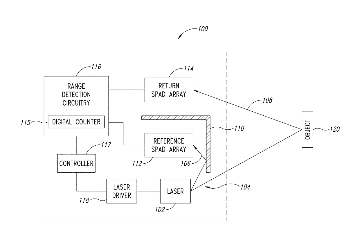
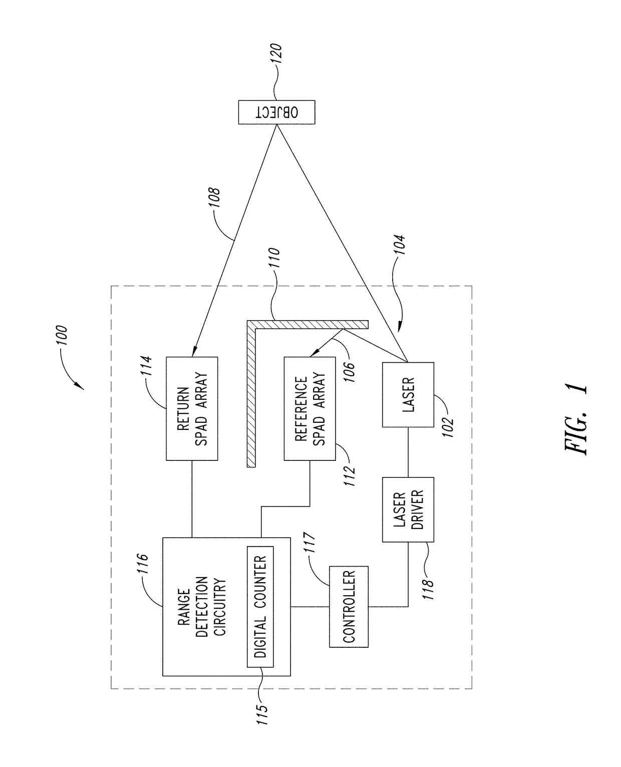
[0018]FIG. 1 is a block diagram illustrating an adaptive laser power and ranging limit TOF range detection device 100, in accordance with one or more embodiments. As shown in FIG. 1, the TOF range detection device 100 includes a laser 102 for generating and transmitting an optical pulse 104 into an image scene, which may contain an object 120. In one or more embodiments, the laser 102 is a vertical cavity surface emitting laser (VCSEL).

[0019]An optical barrier 110 is included in the TOF range detection device 100, and reflects a first portion 106 of the optical pulse toward a reference single-photon avalanche diode (SPAD) array 112. A second portion 108...


PUM


Abstract

A time of flight range detection device includes a laser configured to transmit an optical pulse into an image scene, a return single-photon avalanche diode (SPAD) array, a reference SPAD array, a range detection circuit coupled to the return SPAD array and the reference SPAD array, and a laser driver circuit. The range detection circuit in operation determines a distance to an object based on signals from the return SPAD array and the reference SPAD array. The laser driver circuit in operation varies an output power level of the laser in response to the determined distance to the object.

Description

BACKGROUNDTechnical Field[0001]The present disclosure generally relates to time of flight range detection devices, and more particularly, to time of flight range detection devices having an adaptive laser output power.Description of the Related Art[0002]Ranging devices, such as time of flight (TOF) sensors, are typically used to detect the distance to nearby objects and are able to do so without physically touching the object. Conventional time of flight sensors may be used for object detection, proximity detection, and further may be used to determine an actual range or distance from the device to a detected object. Such devices may be utilized in various electronic devices, such as cameras, phones, including smartphones, vehicles, machinery, and other devices for detecting the distance to nearby objects.[0003]Conventional TOF sensors or devices typically include a light-emitting device (e.g., a laser or a LED), a return or target sensor array, a reference sensor array, and circuit...

Claims


Application Information

Patent Timeline
Patent Type & Authority Applications(United States)
IPC IPC(8): G01S7/484G01S7/486G01S17/10
CPCG01S7/484G01S7/4863G01S17/10G01S7/4868
Inventor YANG, XIAOYONGXIAO, RUIDELEULE, ARNAUD
Owner STMICROELECTRONICS SRL
Why Eureka
Try Eureka