
Position controller for controlling a rotation center of a tilting head

Active Publication Date: 2017-12-14
DN SOLUTIONS CO LTD
View PDF2 Cites 6 Cited by
  • Summary
  • Abstract
  • Description
  • Claims
  • Application Information

AI Technical Summary

Benefits of technology

The present invention provides a method for automatically detecting and correcting the center error of a tilting head in a machining center. This is achieved by using the offset detector in the coordinate system and applying a center correction algorithm based on the rotational transform of the first and second tool offsets. This method allows for accurate and efficient detection and correction of the center error, thereby improving manufacturing accuracy and efficiency. Additionally, the method requires no additional center error detectors or complicated processes.

Problems solved by technology

The machining center involves various inherent errors such as an assembly error, an operation error and an installation error, so that the control position of the tool is necessarily deviated from the actual position.
Since the machining center is made up of various components such as the table, the spindle head and the column, each of the components has its own assembly error that is caused by the assembly of each component and the operation error that is caused by the usage or the operation conditions or environments of each component.
In addition, when each of the components is installed to the machining center, the installation error inherently occur in the machining center.
Therefore, the machining center inherently has the tool offset due to the assembly error, the operation error and the installation error.
However, when the spindle head itself is rotated with respect to its own central axis just like the tilting head, the tool offset of the tool is not sufficiently corrected just by the coordinate correction.
That is, the position error of the rotation center of the tilting head may occur in the corrected coordinate system, and thus the tool offset may be still found in the machining center in spite of the coordinate correction.
Since the tilting head includes its own driver such as a spindle motor for rotating the tilting head as well as a main driver for linearly moving the tilting head, the assembly error, the operation error and the installation error of the spindle motor usually causes the deviation between a control center, which is set to be a rotation center of the tilting head in the numerical controller, and an actual center which is actually measured as a rotation center of the tilting head.
However, since the center error detector is necessarily installed to the table in addition to the offset detector whenever the offset correction is conducted, the preparation processes for the machining center requires high cost and time for the offset correction.
In addition, the manual detection of the center error reduces the accuracy of the detected center error and the manual detection and correction becomes a significant obstacle to the automation of the center error detection and correction.

Method used


Image

  • Position controller for controlling a rotation center of a tilting head
  • Position controller for controlling a rotation center of a tilting head
  • Position controller for controlling a rotation center of a tilting head

Examples


Embodiment Construction

[0028]Example embodiments will now be described more fully with reference to the accompanying drawings. Embodiments, however, may be embodied in many different forms and should not be construed as being limited to the embodiments set forth herein. Rather, these example embodiments are provided so that this disclosure will be thorough and complete, and will fully convey the scope to those skilled in the art. In the drawings, the thicknesses of layers and regions may be exaggerated for clarity.

[0029]It will be understood that when an element is referred to as being “on,”“connected to,”“electrically connected to,” or “coupled to” to another component, it may be directly on, connected to, electrically connected to, or coupled to the other component or intervening components may be present. In contrast, when a component is referred to as being “directly on,”“directly connected to,”“directly electrically connected to,” or “directly coupled to” another component, there are no intervening c...


PUM


Abstract

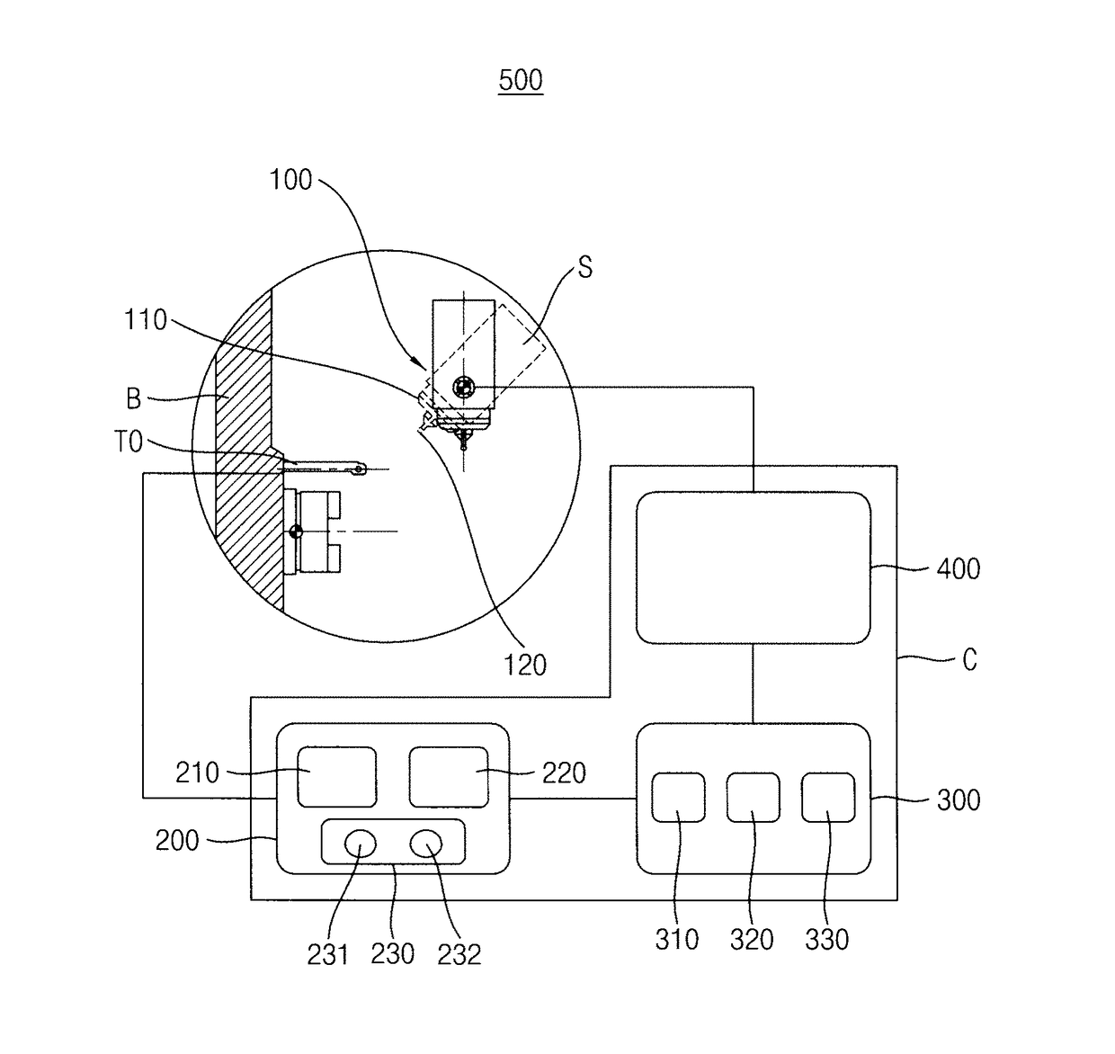
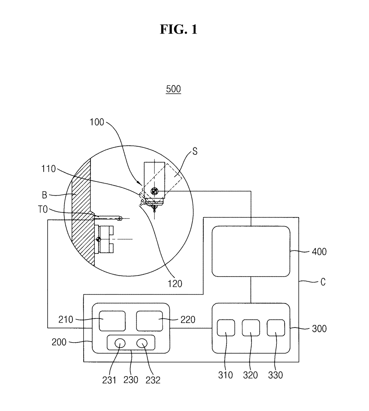
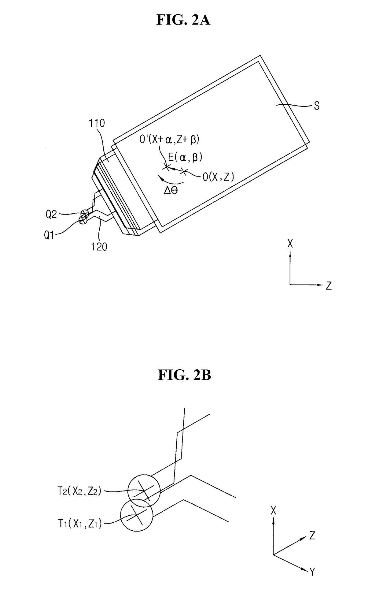
Disclosed is a position controller for a tilting head in a machining center. The position controller includes an offset attachment having a body combined to the tilting head and a spherical contact secured to the body, an offset detector built in the machining center such that the offset detector move out into a process area of the machining center and automatically detects a tool offset from a contact point with the spherical contact, a storing unit individually storing first and second tool offsets by respective rotation positions of the tilting head, and an operator generating a transform offset of the first tool offset by a rotational transform and a center error vector from the transform offset and the second tool offset. Accordingly, the center error of the tilting head is automatically detected and corrected in the machining center.

Description

PRIORITY STATEMENT[0001]This application claims priority under 35 U.S.C §119 to Korean Patent Application No. 10-2016-0073597 filed on Jun. 14, 2016 and Korean Patent Application No. 10-2016-0105060 filed on Aug. 18, 2016 in the Korean Intellectual Property Office, the contents of which are hereby incorporated by reference in their entirety.BACKGROUND1. Field[0002]Example embodiments relate to a position controller for controlling a rotation center of a tilting head, and more particularly, to a position controller for automatically correcting a position error with respect to the rotation center of the tilting head in a machining tool.2. Description of the Related Art[0003]Recently, the demand for complicated and elaborate mechanical products has sharply risen according to the development of the precise mechanical industry such as an automobile industry, a shipbuilding industry and an airline industry. Most of the recent mechanical products tend to be manufactured in a single machini...

Claims


Application Information

Patent Timeline
IPC IPC(8): G05B19/31
CPCG05B19/31G05B2219/50334G05B2219/49178B23Q15/22G05B19/4015G05B2219/37014G05B2219/49121G05B2219/50026G05B2219/50031G05B2219/50137G05B2219/50297
Inventor KIM, HYON-SEOK
Owner DN SOLUTIONS CO LTD
Learn More