Long-distance radio frequency anti-metal identification tag

Active Publication Date: 2017-12-21
READ TAG TECH CORP
View PDF0 Cites 9 Cited by
  • Summary
  • Abstract
  • Description
  • Claims
  • Application Information

AI Technical Summary

Benefits of technology

[0006]Preferably, the slot of the first antenna is a -shaped slot. The slot has a wide slot portion for accommodating the second antenna and a narrow slot portion. The groove is disposed between the narrow slot portion and the side edge. Through the -shaped slot and the width of the groove of the first antenna to match the induction field pattern of the electromagnetic wave signal reflected on the surface of the metal object and to adjust the frequency band and bandwidth of the electromagnetic wave signal. The UHF electronic tag attached to the surface of the metal object for identification can achieve high sensitivity and long-distance reading effects in the frequency band to be used.
[0007]Preferably, the bottom surface of the insulating spacer plate is provided with a double-sided adhesive layer, and a release paper is provided on the double-sided adhesive layer. Only the release paper is torn from the bottom surface of the insulating spacer plate, so that the double-sided adhesive layer can be secured and attached to the surface of any object.

Problems solved by technology

A common microstrip antenna itself has the shortcomings of narrow frequency, resulting in many restrictions on the antenna design.
If it is applied to metal surfaces, such as metal labels, cars (motorcycle) license plates, power facilities and other fields, the signal is easily reflected to result in abnormal reception.
Although the above-mentioned patent

Method used


Image

  • Long-distance radio frequency anti-metal identification tag
  • Long-distance radio frequency anti-metal identification tag
  • Long-distance radio frequency anti-metal identification tag

Examples


Embodiment Construction

[0021]Embodiments of the present invention will now be described, by way of example only, with reference to the accompanying drawings.

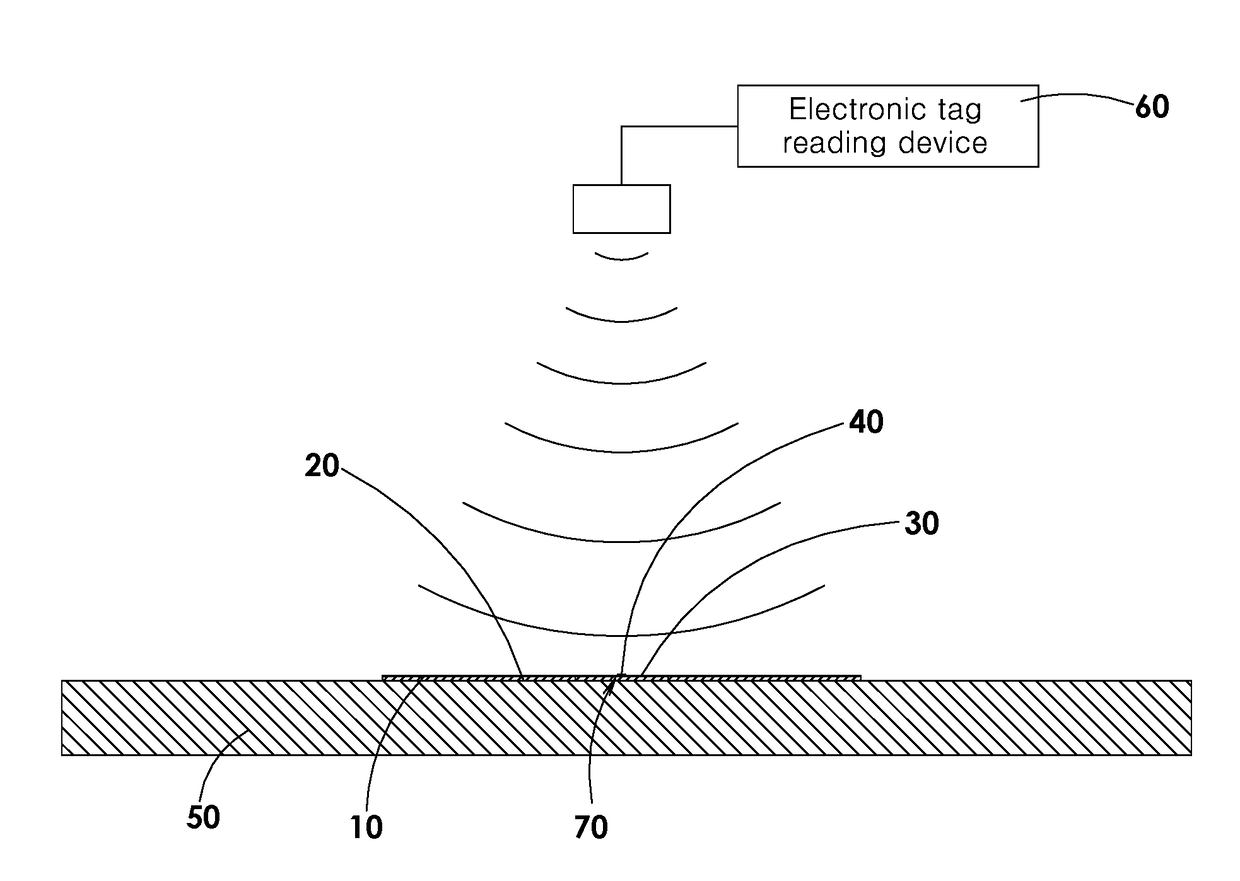
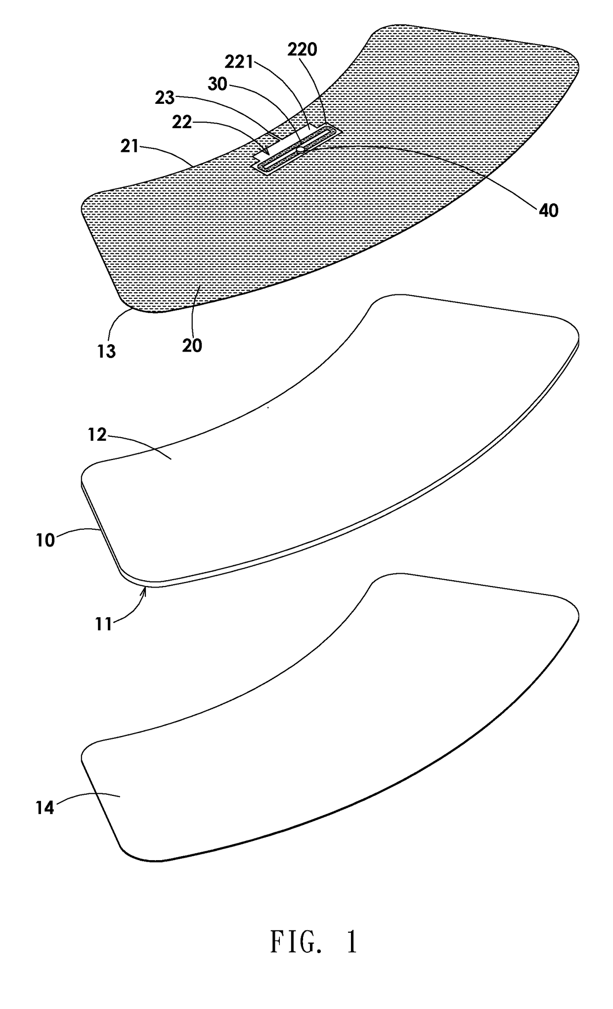
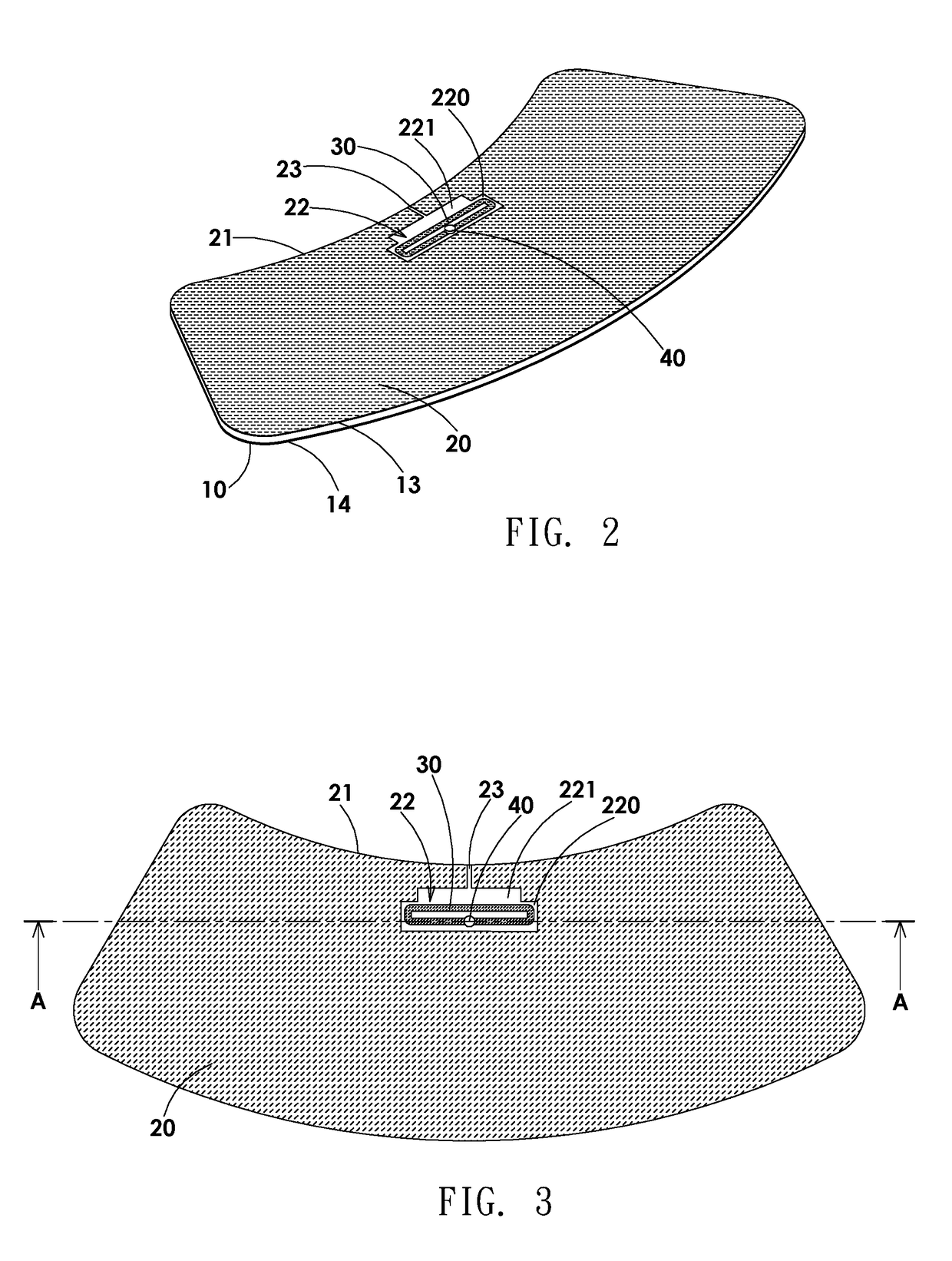
[0022]A long-distance radio frequency anti-metal identification tag, as shown in FIGS. 1-5, is an ultra high frequency electronic tag (UHF TAG), and comprises at least one insulating spacer plate 10, a first antenna 20, and a second antenna 30. The insulating spacer plate 10 is made of a non-metal non-conductive insulating material and has a bottom surface 11 and an upper surface 12. The first antenna 20 is a metal or non-metal conductive foil antenna sheet attached to the upper surface 12 of the insulating spacer plate 10. The first antenna 20 has a slot 22 near one side edge 21 thereof. A groove 23 is provided between the side edge 21 and the slot 22. The shape and size of the slot 22 and the width of the groove 23 are configured to adjust the induction frequency band / bandwidth and the induction field pattern of an electromagnetic wave signal. The s...


PUM


Abstract

A long-distance radio frequency anti-metal identification tag is provided. When a bottom surface of an insulating spacer plate is attached to the surface of a metal object and an electronic tag reading device is used to read a radio frequency identification chip on a second antenna. A resonant cavity is formed between a slot of a first antenna and the surface of the metal object through the isolation of the insulating spacer plate, such that the second antenna located at the position of the resonant cavity resonates with an electromagnetic wave signal reflected on the surface of the metal object by the first antenna. The electromagnetic wave signal is transmitted to the radio frequency identification chip, or the feedback signal of the radio frequency identification chip is transmitted out. The overall UHF electronic tag is resistant to a metal interference and has the performance of long-distance reading.

Description

FIELD OF THE INVENTION[0001]The present invention relates to a long-distance radio frequency anti-metal identification tag that is resistant to metal interferences and achieves long-distance read effects, meeting the economic benefits.BACKGROUND OF THE INVENTION[0002]Radio frequency identification (RFID) technology has been widely used in industrial automation, commercial automation, transportation and control management, and many other fields. More and more researches study UHF RFID systems to achieve long-distance, high efficiency, low cost and other characteristics. Because RFID has the advantages of non-contact, low cost, high security and mass production, traditional two-dimensional bar codes are gradually replaced by RFID. These days, radio frequency identification (RFID) is also widely used in identity identification, access control, vehicle management, warehousing logistics, retail, security management, forest management, and many other fields. A common microstrip antenna it...

Claims


Application Information

Patent Timeline
IPC IPC(8): H01Q1/22H01Q7/00H01Q1/38H01Q13/18G06K19/077
CPCH01Q1/2225H01Q7/00H01Q1/38H01Q13/18G06K19/07786G06K19/07749G06K19/07771
Inventor WU, CHI JUCHANG, SHIRL MEICHAN, ALEXANDERTING, CHIN HSIENCHAN, HSI JUI
Owner READ TAG TECH CORP
Why Eureka
Try Eureka