
Beam reporting and scheduling in multicarrier beamformed communications

Active Publication Date: 2017-12-21
QUALCOMM INC
View PDF19 Cites 14 Cited by
  • Summary
  • Abstract
  • Description
  • Claims
  • Application Information

AI Technical Summary

Benefits of technology

This patent discusses wireless communication systems that use mmW frequency ranges, which are associated with increased signal attenuation. To overcome this, beamforming techniques are used to combine energy and improve signal quality. However, due to the increased path loss, transmissions from the UE may also be beamformed. In lower frequency bands, beamformed communications are used to improve reliability. Overall, the patent aims to improve wireless communication systems using mmW frequency ranges and beamforming techniques.

Problems solved by technology

Due to the increased amount of path loss in beamformed communications systems, transmissions from the UE may be beamformed.
However, the unique challenges of heavy path-loss faced by beamformed communication systems may result in the use of analog beamforming, which may have or use new functionality when combined with CA.

Method used


Image

  • Beam reporting and scheduling in multicarrier beamformed communications
  • Beam reporting and scheduling in multicarrier beamformed communications
  • Beam reporting and scheduling in multicarrier beamformed communications

Examples


Embodiment Construction

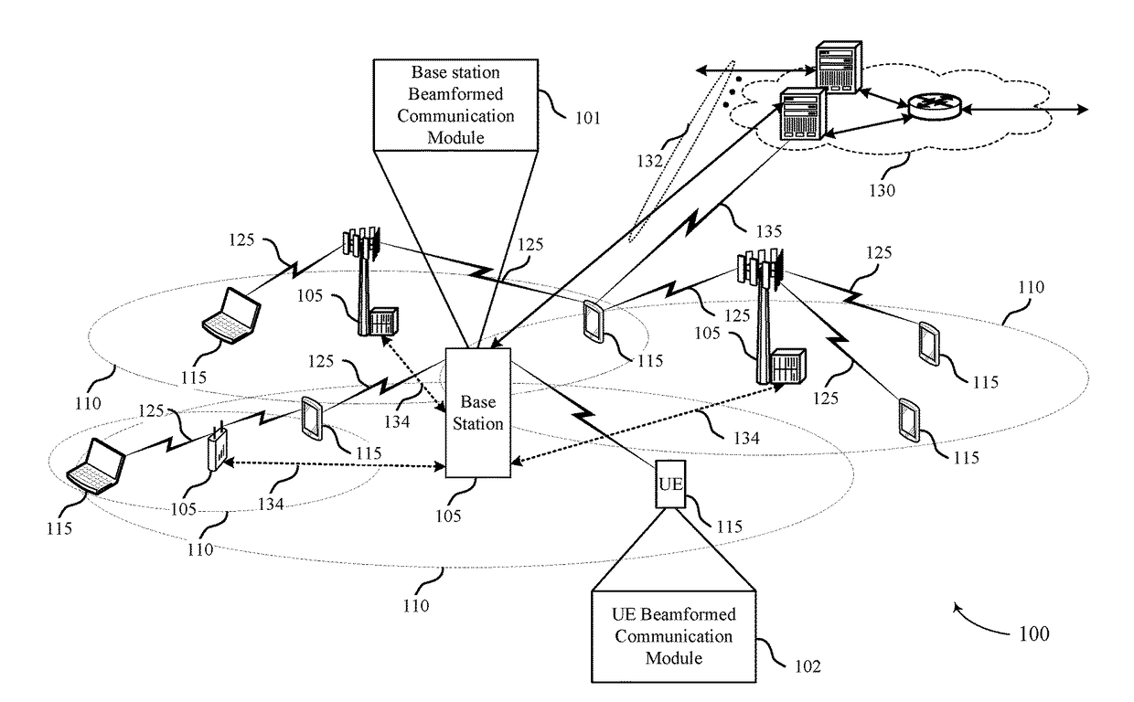
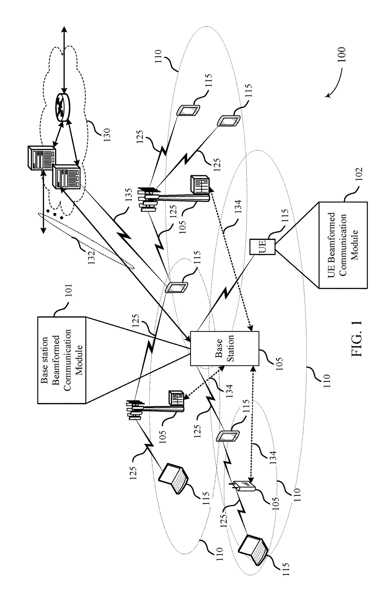
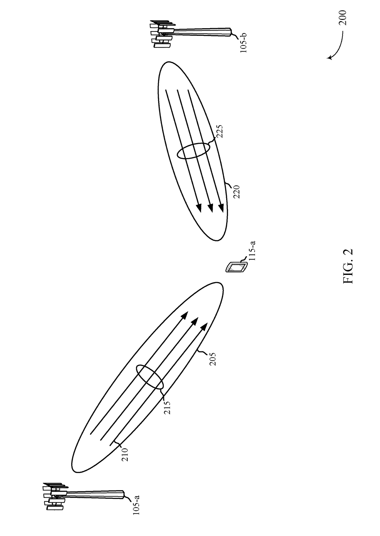
[0040]In a multicarrier beamformed communication system, the multiple component carriers may share the same antenna panels, in which case, the beams from the carriers will point in the same direction (e.g., a single beam carries all the carriers). Alternatively, the carriers may be divided into groups, where carriers in the same group use the same panel while those in different groups use different panels. In this case, the beams from different groups may be pointed in different directions. In LTE, due to frequency selectivity across multiple carriers, the UE measurement and reporting may be done separately on each component carrier. The frequency selectivity could arise in beamformed communication systems as well. However, if the beams from all the component carriers within a group of component carriers are known to be in the same direction at the transmitter, then beam related UE measurements may be combined across multiple component carriers.

[0041]For example, with separate measu...


PUM


Abstract

Methods, systems, and devices for wireless communication are described. A base station may partition a plurality of carriers into one or more groups. Each carrier within a group may share one or more antenna panels so as to each be directed by a transmit beam in a same direction. The base station may transmit to a user equipment a carrier group indication that identifies the partitioning of the plurality of carriers into the one or more groups and maps a group identifier for at least one of the one or more groups to a beam identifier that identifies the corresponding transmit beam.

Description

CROSS REFERENCES[0001]The present application for patent claims priority to U.S. Provisional Patent Application No. 62 / 350,630 by Akkarakaran, et al., entitled “Beam Reporting and Scheduling in Multicarrier Millimeter-Wave Communications,” filed Jun. 15, 2016, assigned to the assignee hereof.INTRODUCTION[0002]The following relates generally to multicarrier beamformed wireless communication, and more specifically to beam reporting and scheduling in multicarrier beamformed communications.[0003]Wireless communications systems are widely deployed to provide various types of communication content such as voice, video, packet data, messaging, broadcast, and so on. These systems may be capable of supporting communication with multiple users by sharing the available system resources (e.g., time, frequency, and power). Examples of such multiple-access systems include code division multiple access (CDMA) systems, time division multiple access (TDMA) systems, frequency division multiple access...

Claims


Application Information

Patent Timeline
IPC IPC(8): H04W24/10H04L5/00H04W16/28H04L29/08H04W88/02H04W88/08
CPCH04W24/10H04W16/28H04W88/08H04L5/0051H04W88/02H04L67/303H04B7/0617H04L5/001H04L5/0023H04L5/0092H04L5/14
Inventor AKKARAKARAN, SONYLUO, TAONAGARAJA, SUMEETH
Owner QUALCOMM INC
Learn More