
Control Method and Device for Cutter Shaped by Helical Spring

Active Publication Date: 2017-12-28
LIN BINGNAN
View PDF1 Cites 0 Cited by
  • Summary
  • Abstract
  • Description
  • Claims
  • Application Information

AI Technical Summary

Benefits of technology

The present invention is a coil spring forming machine that uses a virtual reference point and relative coordinate to simplify the calculation process. This machine is operated by controlling the displacement of the coil spring bending tools based on the radius of the coil spring. The result is a more efficient and one-dimensional calculation. The technical effect of this invention is to provide a more efficient and simplified process for creating coil springs.

Problems solved by technology

Especially for producing a coil spring with multiple diameters like hourglass-shaped, olive-shaped or cone-shaped, the numerical control motor sometimes needs to wait for the high-end computer to complete the complex calculation which leads to cost increase and prevents automation of small size coil spring forming machine.

Method used


Image

  • Control Method and Device for Cutter Shaped by Helical Spring
  • Control Method and Device for Cutter Shaped by Helical Spring
  • Control Method and Device for Cutter Shaped by Helical Spring

Examples


first embodiment

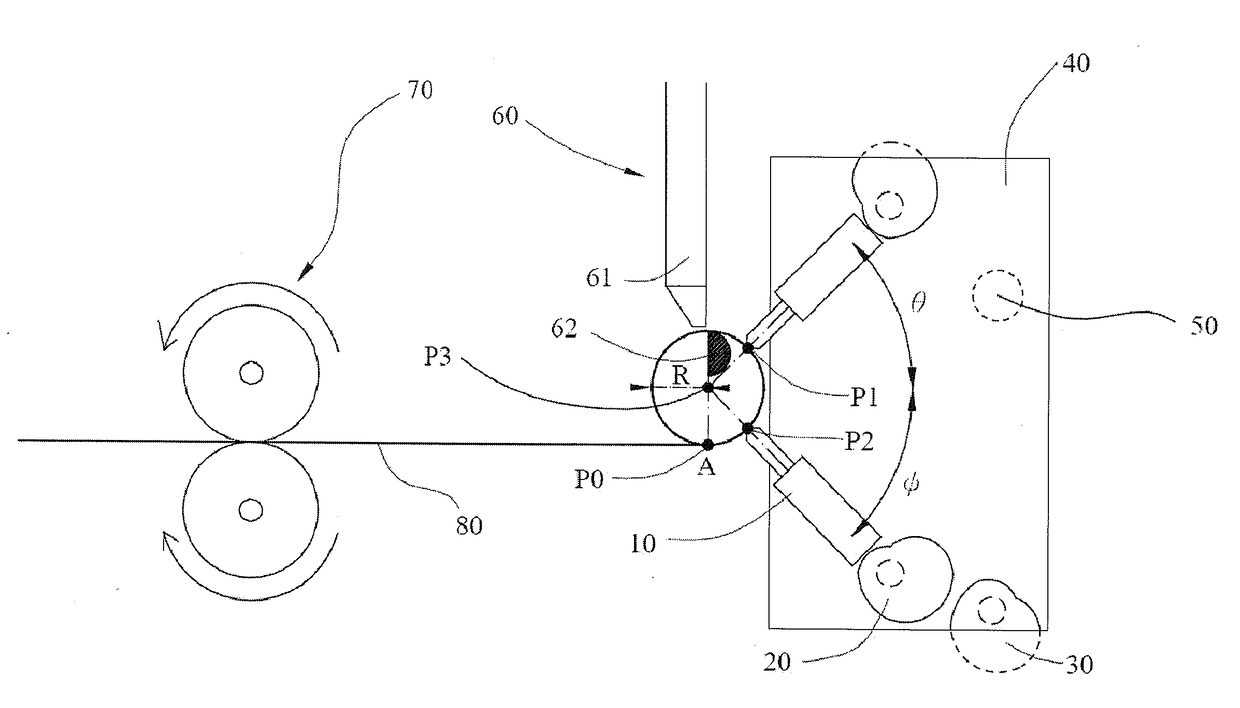
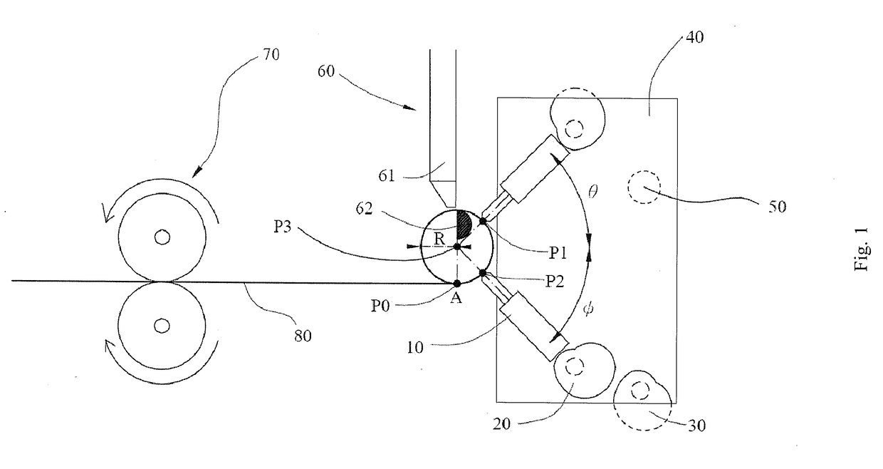
[0042]Each coil spring bending tool 10 is respectively connected with each controlling apparatus 20. The at least two controlling apparatuses 20 control the distance between the at least two coil spring bending tools 10 and the virtual reference point to form the coil spring with different radius. The at least two controlling apparatuses 20 are mounted on the assembling platform 40. A tip of the coil spring bending tool 10 is continually contacted with an outer surface of the coil spring. The distance between the tip of the coil spring bending tool 10 and the virtual reference point is maintained in equidistance so that a displacement of the at least two coil spring bending tools 10 will remain the same while the radius of the coil spring is changing. Aforementioned displacement is an extend or retraced distance of the at least two coil spring bending tool 10 when changing the radius of the coil spring. Moreover, according to a mechanical tolerance or demands of actual use, the disp...

second embodiment

[0043]When three coil spring bending tools 10 are used in the present invention, the third coil spring bending tool 10 may be placed between the first and the second coil spring bending tools 10. The third coil spring bending tool 10 may provide extra bending force and prevent distortion of the coil spring away from a perfect circle according to material property or radius of the spring wire 80.

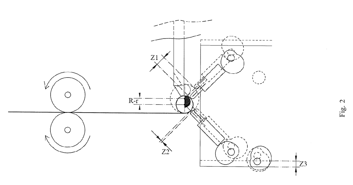
[0044]The lifting apparatus 30 is connected with the assembly platform 40 to adjust a height displacement of the assembly platform 40. The height displacement is a distance between the assembly platform 40 and ground. The virtual reference point will adjust according to the displacement of the assembly platform 40. The controlling apparatus 20 controls the height displacement of the assembly platform 40 with respect to an absolute point the present invention.

[0045]With reference to FIG. 3, a third embodiment of the present invention is disclosed. The height between the virtual reference point...


PUM

PropertyMeasurementUnit
Forceaaaaaaaaaa
Poweraaaaaaaaaa
Diameteraaaaaaaaaa

Abstract

Disclosed are a control method and a device for a cutter shaped by a helical spring, which comprises two cutter position controlling devices (20) connected to two spring outer diameter cutters (10) respectively and comprises a cutter lifting device (30). The two cutter position controlling devices (20) are arranged in the same mounting plane (40). The cutter position-controlling device (20) controls an amount of displacement of the stretching and retracting of the two spring outer diameter cutters (10). The amount of displacement of the spring outer diameter cutters (10) and the amount of up and down movement of the mounting plane (40) are controlled simultaneously by a motor (50). By applying the concept of relative coordinates, the requirements of control can be simplified from two two-dimensional control movements to three single-axis linear movements by using the centre (P3) of a spring coil as the origin of the coordinates for the movement of the spring outer diameter cutter. In the case that the distances of linear movement on the three axes are identical or at a fixed ratio, the advantage of reducing the number of motors is achieved.

Description

BACKGROUND OF THE INVENTION1. Field of the Invention[0001]The present invention relates to a controlling device, and more particularly to a controlling device for coil spring bending tool and controlling method thereof.2. Description of Related Art[0002]Device for controlling an outer diameter of a coil spring in a conventional coil spring forming machine has shortcomings of being produced in high cost and difficulty for operation. For example, most advanced countries like US or European normally use multi-axis numerical control motors to control an automatic machine. Japan otherwise uses two numerical control motors to control each coil spring bending tool of the conventional coil spring forming machine. Since at least four numerical control motors were used, an absolute coordinate is therefore adopted to the conventional coil spring &Inning machine.[0003]The absolute coordinate is engaged of obtaining locations of each coil spring bending tool by calculating trigonometric function...

Claims


Application Information

Patent Timeline
IPC IPC(8): B21F3/02B21F35/00
CPCB21F3/02B21F35/00B21F3/06
Inventor LIN, BINGNAN
Owner LIN BINGNAN
Learn More